Rightmark was how I started as well. It works pretty well for basic info as you say.
I just bought a bunch of 12v halogen bulbs from eBay and want to connect them series parallel to reduce the intensity of the resistive light on my LuFo Lite amp.
I need time to play with these simple amps. They are so much fun.
I just bought a bunch of 12v halogen bulbs from eBay and want to connect them series parallel to reduce the intensity of the resistive light on my LuFo Lite amp.
I need time to play with these simple amps. They are so much fun.
I know this one by Juma (a BJT based F5 HPA) is 24 parts and double the limit but topologically simple and I have the PCBs as Prasi gave them to me. I really want to try it.
I will measure the fr response with both headphones, planar and dynamic. Will see what we get. It sounds good. Distortion is low, ~0.072% at pretty high level. The 1kHz spectrum I posted is with asymmetric resistors, upper one at 8 ohms, lower one at 2 ohms.
Quoting myself here, i measured fr response for Juma's circuit with dynamic and planars connected. The same conditions for both, slightly lower lovel, close to -10dB as oposed to -5 dB i normaly use. Luckily i do not wear the headphones during measurement.
Long story short, there is a difference. Planars with flat resistance have flatter response. Dynamic headphones have hump around 100Hz, likely fs?
Bummer is, there is rolloff at highs. Not sure why.
Attachments
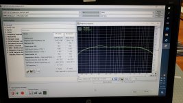
It’s only 1.5dB roll off but I don’t see what would cause it. There is no low-pass cap and resistor RC to ground anywhere.
Well this would not be complete with a trip down memory lane to my early beginnings in audio : "Szekeres headphone amp"
I seem to have come full circle 🙂
..dB
I seem to have come full circle 🙂
..dB
@X do you have a link to the JUMA BJT/F5 amp - I am looking to build an F5 esque amp for a friend ( headphone amp )
quite simple ....X do you remember if you like ??And yet is another I made with the BF862 and LU1014D back in 2016:
MOSFET Source Follower Headamp
Yes, the BF862 and LU1014D sounded very good. I even put it in a chassis which I rarely do. If I have time I will revisit the chassis and fix some grounding errors I made back then as a novice DIY amp builder. I had no concept of “dirty” vs “clean” grounds back then. But it was a nice headphone amp. I do recall it needed a circa 4.7ohm series resistor at the output before the headphone jack. Or else it made a screeching sound when headphone was plugged in. 2-4 KHz oscillation.
I have been using 2SK209GR's. Not a simple substitution as it requires minor tweaking of DC setpoints as Idss is different.
Yes - my DCA amp has provision for either and there is a table for changes to resistor setpoints depending on choice. Please look in thread for DCA.
Or is your question, can 2SK170BL be used with LU1014D? Yes, but I would need to run LTSpice to dial in setpoints.
Or is your question, can 2SK170BL be used with LU1014D? Yes, but I would need to run LTSpice to dial in setpoints.
I have been using 2SK209GR's.
Hey thanks, I can manage sourcing that apparently.
That's cool because attempting to source and build with unobtainium is no fun. Sometimes, even their substitutions are out of stock or obsolete.
Quoting myself here, i measured fr response for Juma's circuit with dynamic and planars connected...
Bummer is, there is rolloff at highs. Not sure why.
Hey, Adason.
Did you experiment any further with the version of this amp you built for speakers? Any change to the schematic?
What’s On the Bench Tonight (OBT)
I have some LUD's on the way and may start my power JFET fun with your brilliantly simple amp.
I got the solder out and assembled everything together for the BF862/IRF610 combo. A bit disappointed because I used a 24V smps brick and the Juma Easy Peasy Cap Multiplier with an IRF610 mosfet. SMPS voltage was 24.5V and I measured the Cap multiplier voltage at 21.5V, so not the expected 20V or so. When I connected each pcb to the cap multiplier, voltage went UP to 23.8V and now looks like there is no voltage drop at all. Maybe the IRF610 died.
I grabbed a variable linear supply and dialed it in to 20V and verified that the voltages appear close to what was indicated in the sim. I'll play a bit more with the cap multiplier circuit. I have several IRF610s in my parts stock, so I'll swap it out and see if I get closer to the target voltage. I'll probably check both amplifier boards to make sure I don't have a short somewhere.
I grabbed a variable linear supply and dialed it in to 20V and verified that the voltages appear close to what was indicated in the sim. I'll play a bit more with the cap multiplier circuit. I have several IRF610s in my parts stock, so I'll swap it out and see if I get closer to the target voltage. I'll probably check both amplifier boards to make sure I don't have a short somewhere.