This thread is dedicated to the discussion of simple amps. The only requirement is that it have about 12 or fewer components. These will usually all fit inside your fist, hence the thread title. For those using SMT parts, you could fit 2000 parts in your fist so that doesn't count! 🙂
I have built several myself, and I always find that they sound very good, honest, and oftentimes, very lifelike with a super quiet background.
I think my Pocket Class A amp was the first one.
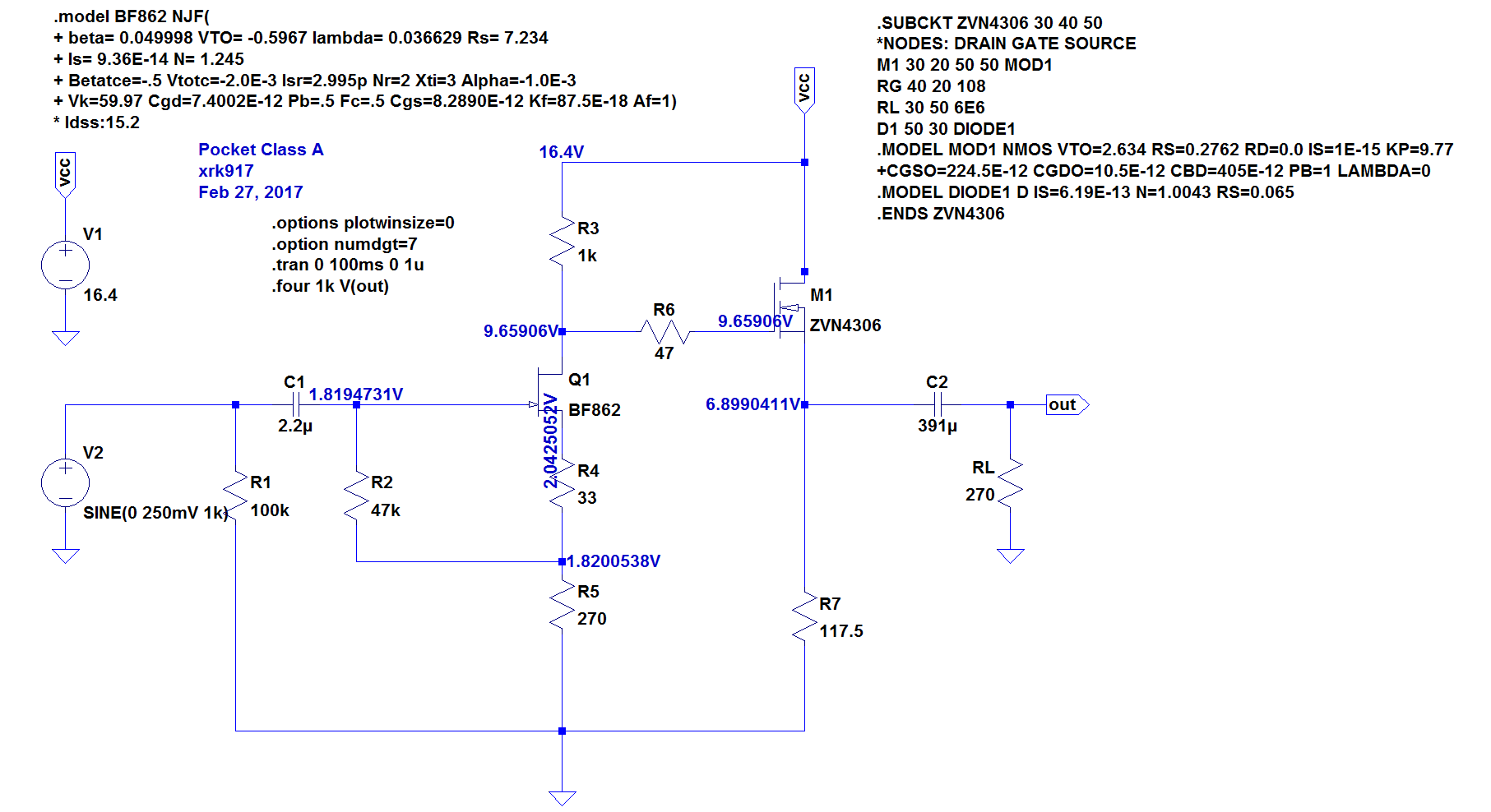
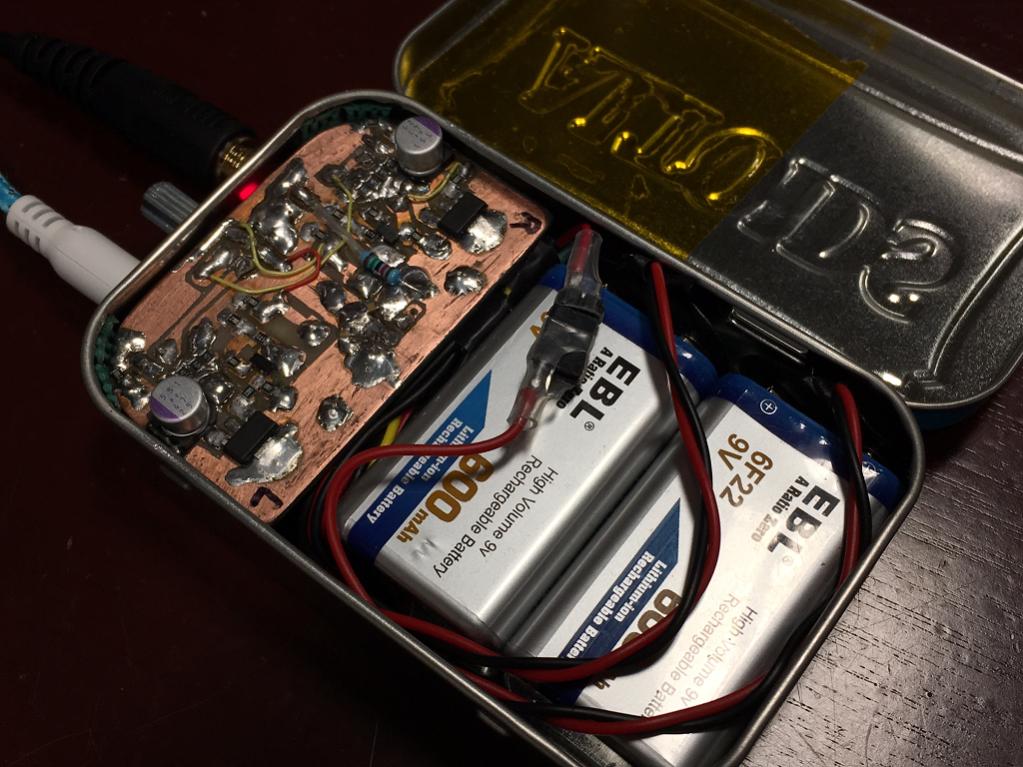
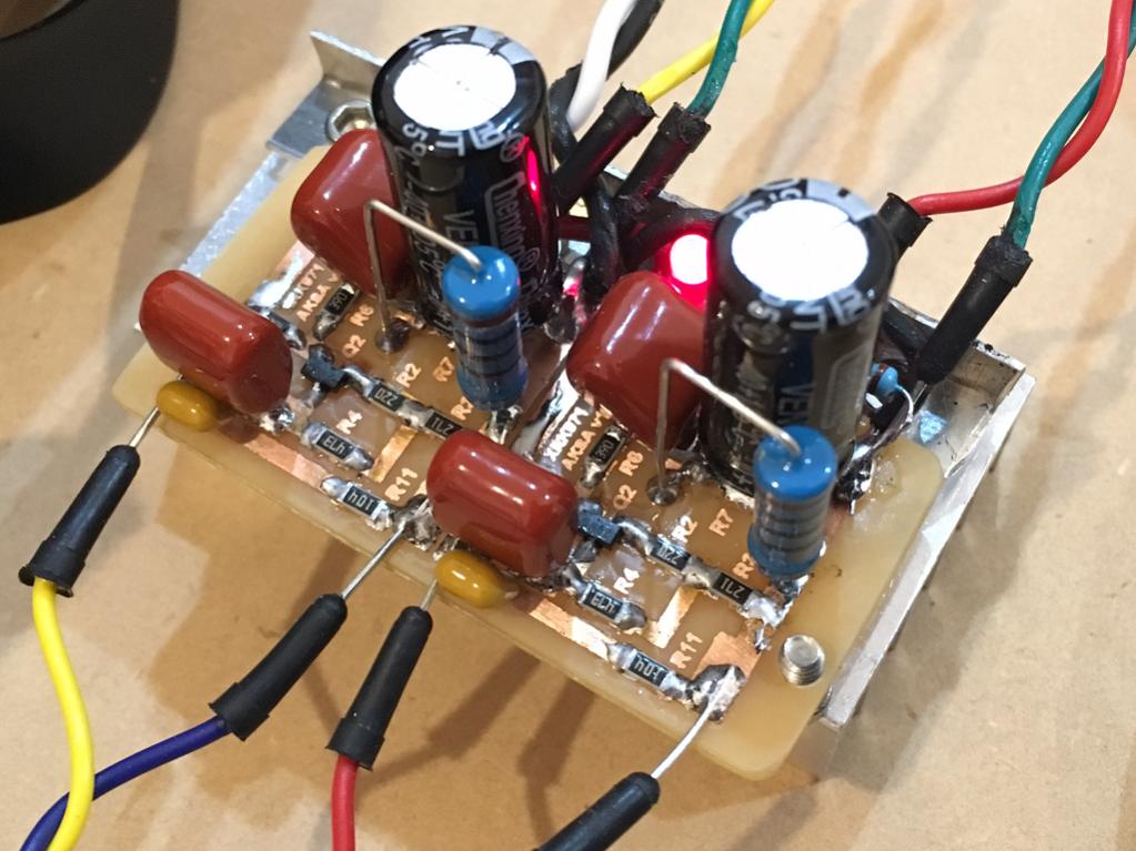
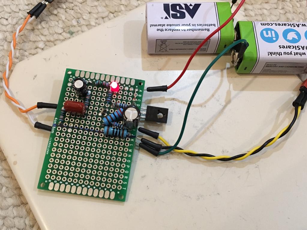
Hand etched PCB using Sharpie marker as acid resist:
I think Adason made Juma's LU1014D headphone amp, that certainly qualifies.
have fun!
I have built several myself, and I always find that they sound very good, honest, and oftentimes, very lifelike with a super quiet background.
I think my Pocket Class A amp was the first one.
Hand etched PCB using Sharpie marker as acid resist:
I think Adason made Juma's LU1014D headphone amp, that certainly qualifies.
have fun!
Last edited:


I was thinking more along the lines of Ennio Morricone... 🙂
A Fistful of Dollars • Main Theme • Ennio Morricone - YouTube
A Fistful of Dollars • Main Theme • Ennio Morricone - YouTube


Agreed!
Even though it’s from an entirely different Clint movie, I tell my kids all the time, “We’re goin’ on a Missourrah BOAT rahde.”
Even though it’s from an entirely different Clint movie, I tell my kids all the time, “We’re goin’ on a Missourrah BOAT rahde.”
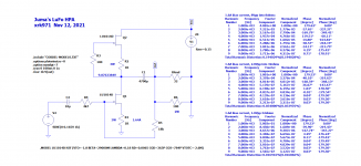
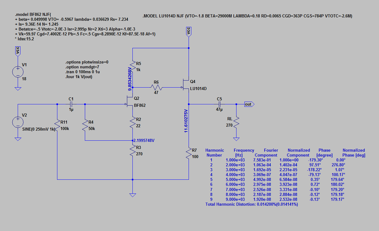
Here is Juma's LU1014D HPA that Adason was building in LTspice. Seems to work well as a headphoneamp with a pretty heavy 1.64A bias current. Changing the source resistorsto larger values (they need to be the same value though) will drop the bias current. 10R will get about 175mA, for example. One thing that is strange is that the gain changes with the load. This is not good for speakers or headphones that have variable impedance - it will cause a non-flat frequency response. For example, at 8ohms, the peak output is about 750mVpp whereas the output was 1000mVpp for 32ohms. This is with 330mVpp input.
Schematic:

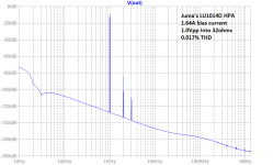
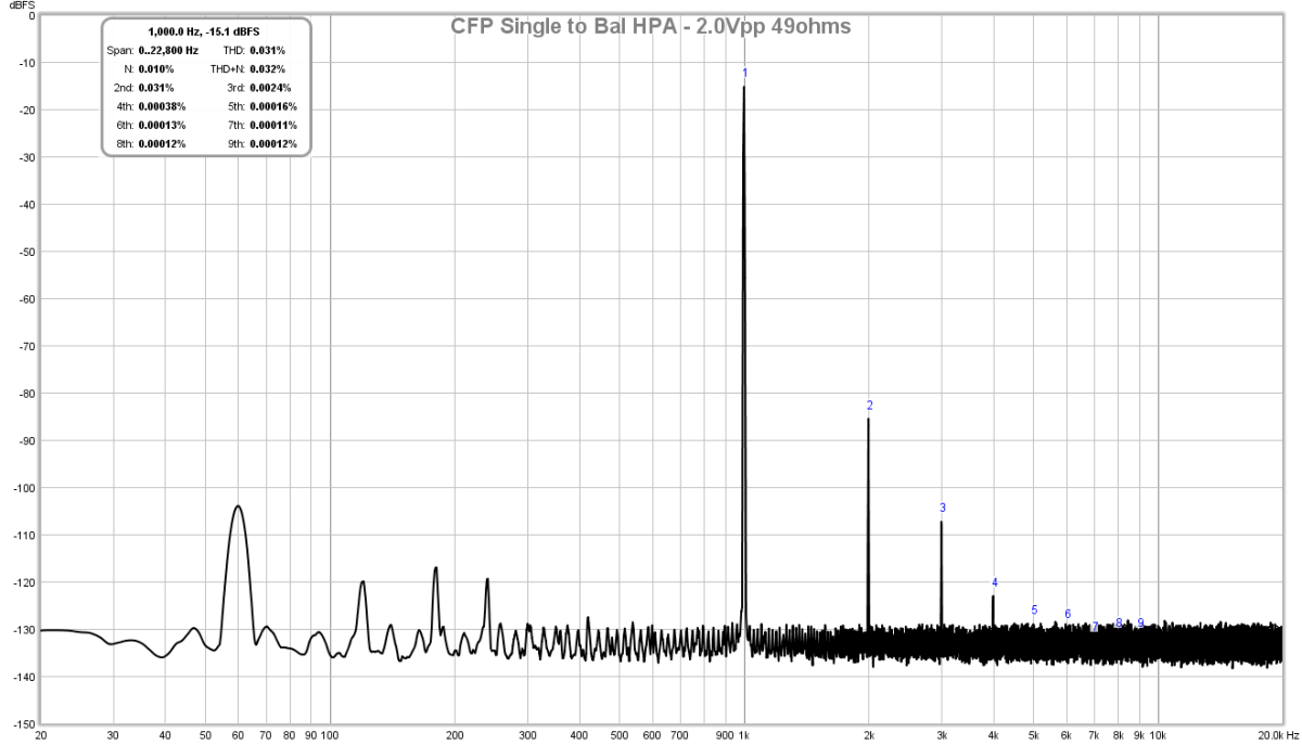
FFT for 1.0Vpp into 32ohms:

Looks like a nice harmonic profile.
Schematic:
FFT for 1.0Vpp into 32ohms:
Looks like a nice harmonic profile.
Attachments
Last edited:
Another great line from Gran Torino. "Ever noticed how you come across somebody once in a while that..."
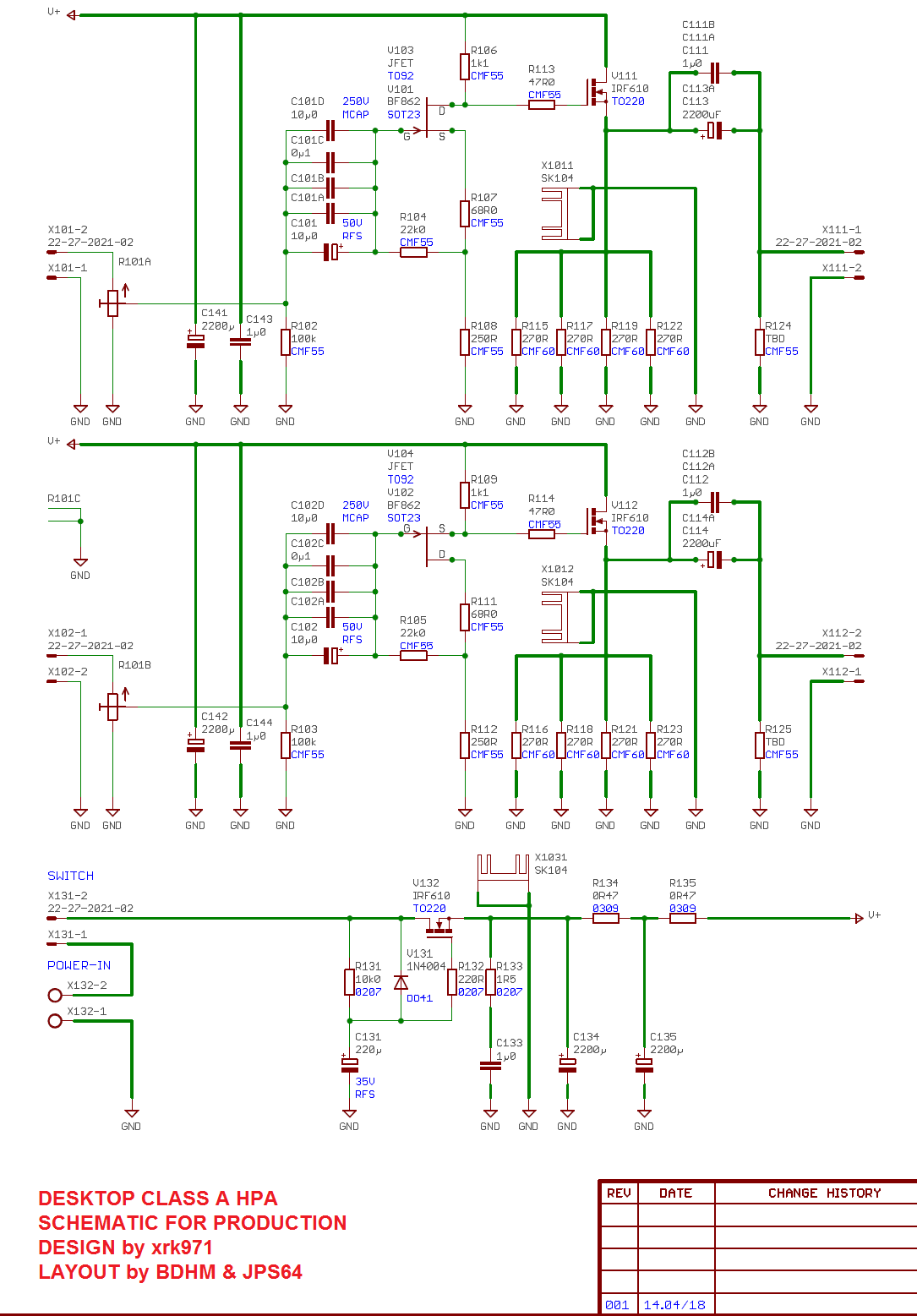
I laid out a pcb for the BF862/IRF610 combo that you detailed in that thread. I plan on finishing it up soon. No doubt it will sound really good.
The BF862 and IRF610 work really well. There is the DCA which helps simplify assembly and provides a cap Mx PSU. Some of the parts are redundant to allow options for different input caps and to spread heat over 4 resistors below the mosfet source. It’s the same amp as the PCA above.
xrk971 Desktop Class A (DCA) Headphone Amp
xrk971 Desktop Class A (DCA) Headphone Amp
Last edited:
Another one from Aksa and it’s SE to balanced drive conversion. If you strip it down to the essential parts it is under 12 parts.
Balanced Drive 2 Transistor SE Class A Headphone Amp
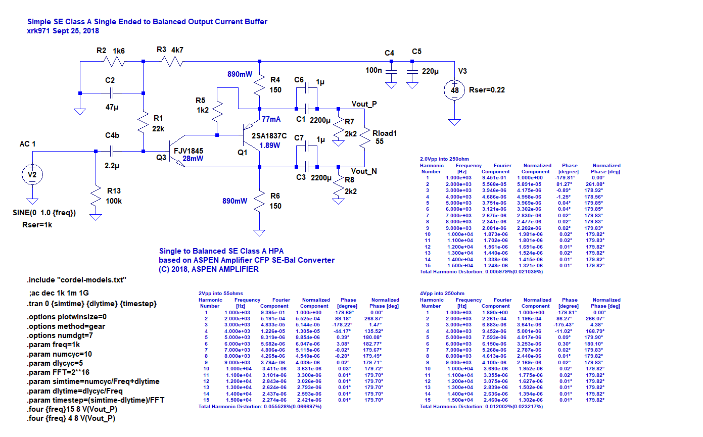
Balanced Drive 2 Transistor SE Class A Headphone Amp
Here is Juma's LU1014D HPA that Adason was building in LTspice. Seems to work well as a headphoneamp with a pretty heavy 1.64A bias current. Changing the source resistorsto larger values (they need to be the same value though) will drop the bias current. 10R will get about 175mA, for example. One thing that is strange is that the gain changes with the load. This is not good for speakers or headphones that have variable impedance - it will cause a non-flat frequency response. For example, at 8ohms, the peak output is about 750mVpp whereas the output was 1000mVpp for 32ohms. This is with 330mVpp input.
Schematic:
FFT for 1.0Vpp into 32ohms:
Looks like a nice harmonic profile.
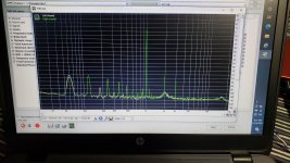
I got this measured.
Why do you say resistors needs to be of same value, just curious. Upper current source can be independently set.
Its interesting that feedback can cause non-flat response with variable resistance load, weird.
Thanks for doing the simulation.
Few comments. Juma specifued 100ohm resistor, parallel to speaker, as 2watts. There is absolutely no voltage on output, no current through that resistor, no need for wattage.
On the other hand, those 1-2ohm resitors he specified for 2 watts, need to be 20watts.
Attachments
Hi Adason,
In my simulations, when I made those resistors non equal, the output clipped and was very asymmetric. Thanks for making measurements. The THD is quite low. Maybe the parallel resistor to the load is to ensure that it never drops below 200ohms in which case something strange happens?
How does it sound to you? Is there any strange frequency response anomaly as headphones in general don’t have flat impedance curves (except for planar magnetic or AMTs).
I will measure the fr response with both headphones, planar and dynamic. Will see what we get. It sounds good. Distortion is low, ~0.072% at pretty high level. The 1kHz spectrum I posted is with asymmetric resistors, upper one at 8 ohms, lower one at 2 ohms.
Hi Adason,
Have you ever tried REW for doing FFTs and frequency response? It gives a lot more freedom on settings of the FFT and the display and plots look easier to read etc.
Howto - Distortion Measurements with REW
Have you ever tried REW for doing FFTs and frequency response? It gives a lot more freedom on settings of the FFT and the display and plots look easier to read etc.
Howto - Distortion Measurements with REW
Yes, I tried, it works for me. I just have REW set up for speaker measurements now. I know that RightMark audio analyzer is not best, but it will do for now.