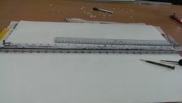
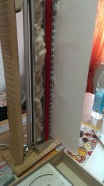
You can control the solder if you put it on the solder tip. The aluminium is so thin you dont need to heat it with the iron. In the pic. the alu strips are 3,5 mm.
Hi Jensen,
I didnt understant what you meant. Could you be more explicit please?
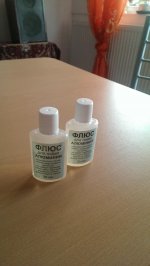
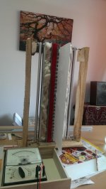
Hey Wrine look what i bought in the pic bellow. It looks like the romanian seller is trusty. I just received them. I cant wait to start tomorrow the work at the ruban.
Cheers
Sergiu
Attachments
Hi Jensen,
I didnt understant what you meant. Could you be more explicit please?
Hey Wrine look what i bought in the pic bellow. It looks like the romanian seller is trusty. I just received them. I cant wait to start tomorrow the work at the ruban.
Cheers
Sergiu
like in the photo. Then the solder is pre-heated, and there is no need too pre-heat the aluminium .
Attachments
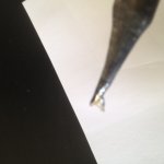
like in the photo. Then the solder is pre-heated, and there is no need too pre-heat the aluminium .
Hi Jensen,
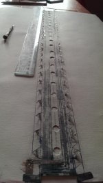
I just finished the bonding process for the membrane for the other ruban. There is no need for further clarification about the solder.. The russian substance that Wrine recomended and i buyed is just perfect. I can say that this is the best aquisition for this year. No more headake with the Al soldering. Now the solder just sticks to the Al faster then on copper, just stunning. Thanks again Wrine for this genious hint. Im glad that i buyed two botles of that flux..
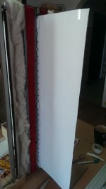
I dont know if you can see from the pics atached bellow but now i atached Al leads for the coil to outside of the cilinders. This will improve for shure the contact from the upper coil where i used copper leads in the past.
I have to make the cuts next week and assemble the second ruban and then tests will show off if i did the mic psu correctly. Fingers crosssed.. 😀
This time i used adhesive Al tape instead of backing Al foil for the coil and the results arent so great because the coil resistance is too low, to be more specific the resistance is 4 ohms now.. We should see the results.
Cheers
Sergiu
Attachments

Good job ! he sergiu !! i bought these flux
Flux Used for Soldering of Aluminum Stainless Steel Nickel Copper | eBay
to solder aluminium , only 3 dollar. and it works great i tested it on some alumnium foil works, i just used some ordinairy electronics solder and it was stuck right away!!! i am very very pleased and impressed. (for once stuff does what it says it does 🙂)
Thanks a lot for this hint. Used to have solder with this stuff inside. Did the 2m-foil speaker we had at ETF.04 with it. At a tweeter shootout not too long ago, my friend and i dropped out because we couldn't get the alu soldered, perhaps the flux cores evaporated from the solder wire (??).
Had we had this stuff, i'm sure we'd won with a tweet-only version of said speaker, haha
Just bringing this up to hint at the possibility the eBay offer linked may or may not have have an early expiry date. -- Ralph
Last edited:
Things are going well but slow... Easter is aproaching fast here in Romania.. tomorrow i will assemble the second ruban (wich has only a rigid frame and the rest is the same except the cuts). This second one has same specs as the first one (materials and damping) except the cuts .
Cant wait to listen to it.
This time im using a JLH 69 amp. I have to admit that this is a very good amp (and very loud) for only a 10w cap coupled amp (input+output)..
Cheers
Sergiu
Cant wait to listen to it.
This time im using a JLH 69 amp. I have to admit that this is a very good amp (and very loud) for only a 10w cap coupled amp (input+output)..
Cheers
Sergiu
Attachments
nice ! , i myself are still working on some amt's, and work allot 🙁
Sorry to hear that my friend.. 🙁
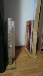
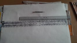
You will miss the party here. Look at the pics bellow. After 4 hour of cutting and thinking I just finished the cuts and thinking how to join the cuts to the frame. What do you say joint them all or stick one and bond the other? I need an advice as fast as you can please.
Every ideea is wellcommed here.
Cheers
Sergiu
Ps: i was thinking about sticking the front alternatively and the back bond it all.
Now the round cuts are bigger and combined with the triangles they will lower even more the central mass.
Attachments
I found that the triangle cuts are FAR more better in centering the coil in the gap than the classic solution with elastics. This way i centered the coil perfectly on both sides. I didnt add so much tension to the triangles ( i sticked them only on the top of each triangle) because i want the coil to move 2 mm. A very elegant solution indeed, Lineaum was right...
Anyway, i sticked all the triangles on one side and alternatly on the other. I have to let them dry now.
Cheers
Sergiu
Anyway, i sticked all the triangles on one side and alternatly on the other. I have to let them dry now.
Cheers
Sergiu
Attachments
Hello my friends,
I have an update for the variant above: it tears your ears apart, that's how loud they are BUT the suspension style is too rigid... It limits the membrane too much. Instead of a wide bander we have a tweeter. Another aspect here is that the "duck voice" installed also. I think that a suited version like this needs a better dampening material for the membrane.
I will not measure it becaise i dont likee it.
An imprortant aspect is that the hights improved very well so i want to unstick some triangles to see how this solution works in a wide bander..
Cheers
Sergiu
Thats to bad but good to know, only triangles makes it to rigid so the resonance will be to high. and it wont allow reproduction under the res frequency. so elastic band it is for now, or a combination. good to see you discover!
Hello my fiend,
I want to report another aspect. I unsticked the triangles and sticked the cilinder only in hinges and not hinges and elastics as before. I added laqueur to the triangles and around them and to the exterior of the coil. The triangles now resonates outside the cilinders now (i lifted them out of the rigid area and the cilinders). The result is that the ruban has a bit more hights than the first and second versions, has even more cleaner voices but the lows are somehow abit limited to about 1khz i think.... 🙁
I will leave them as tey are till tuesday when i want to measure them. Its almost Easter now.
I still have to see is the hights are jnfluenced by how big the cuts are (how low is the mass) and where are they positioned or the triangles style ( not reducing the mass but extending the active portion of the coil outside the cilinders). And i think i will find this soon.
Cheers
Sergiu
Last edited:
Thank you very much my friend. Hope to see you soon back into the game.
Cheers
Sergiu
yeah i am all over the place a t the moment. in terms of the speaker i want to make. so much choices. amt ruba. i indeed must try a ruba with alu coil since that was the one i could not try before since i could not solder it. now we can ofcourse 🙂
need some advise about french Janus membrane suspension
Hi Guys , i'm a french Diyer and have been involved in the Janus adventure for 4 years now.Please be kind about my english that is not very good i just hope you will understand me .
So as it seems that this transducer does'nt interest any french diyer anymore as you can see on the french forums i permit myself to come in your place and share some trick that i've succesfully experienced.
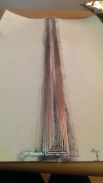
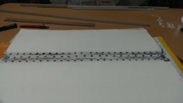
My most difficult issue in building this tranducer has been to keep the bobin in the center of the magnets field from top to bottom . i use "CANSON" paper (for drawing ) 160grams/M2 and it's the best natural sound i've got after having tried several materials : polyethylene, photo paper etc...
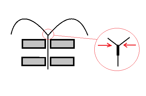
Unfortunatly it is very sensitive to humidity and tends to change the flat bobin to a long spiral that ends by touch the iron bars and add awfull distorsion ! i folded the sheets of paper right close to the bobin as showed on the pic and it reduces drasticaly the deformation of the bobin ( thin printed circuit board with 2X 10 loops ).
I would be glad if some of you had any advice or experience about this
thank you
Hi Guys , i'm a french Diyer and have been involved in the Janus adventure for 4 years now.Please be kind about my english that is not very good i just hope you will understand me .
So as it seems that this transducer does'nt interest any french diyer anymore as you can see on the french forums i permit myself to come in your place and share some trick that i've succesfully experienced.
My most difficult issue in building this tranducer has been to keep the bobin in the center of the magnets field from top to bottom . i use "CANSON" paper (for drawing ) 160grams/M2 and it's the best natural sound i've got after having tried several materials : polyethylene, photo paper etc...
Unfortunatly it is very sensitive to humidity and tends to change the flat bobin to a long spiral that ends by touch the iron bars and add awfull distorsion ! i folded the sheets of paper right close to the bobin as showed on the pic and it reduces drasticaly the deformation of the bobin ( thin printed circuit board with 2X 10 loops ).
I would be glad if some of you had any advice or experience about this
thank you
Attachments

Hi Guys , i'm a french Diyer and have been involved in the Janus adventure for 4 years now.Please be kind about my english that is not very good i just hope you will understand me .
So as it seems that this transducer does'nt interest any french diyer anymore as you can see on the french forums i permit myself to come in your place and share some trick that i've succesfully experienced.
My most difficult issue in building this tranducer has been to keep the bobin in the center of the magnets field from top to bottom . i use "CANSON" paper (for drawing ) 160grams/M2 and it's the best natural sound i've got after having tried several materials : polyethylene, photo paper etc...
Unfortunatly it is very sensitive to humidity and tends to change the flat bobin to a long spiral that ends by touch the iron bars and add awfull distorsion ! i folded the sheets of paper right close to the bobin as showed on the pic and it reduces drasticaly the deformation of the bobin ( thin printed circuit board with 2X 10 loops ).
I would be glad if some of you had any advice or experience about this
thank you
Hi tubegeek,
I made an account on cinetsong one week ago and wanted to invite the other builders from there to here, because we are contributing all from around the world with all sorts of ideas good or bad and testing them.. I didnt make the invite yet because it took aprox two days to accept and approven my account by they'r staff. If you can please make an invite there. I understand french quite well (because of building the Hiraga Super Classe A amp and the Janus 50 from french articles and from cinetsong and other sources) but i still use google translate for posting wich is not accurate..
My english is not so good but we understand each other well wich is very good.
You can see that we had and test allot of ideeas back into the past of this thread in this forum. This thread is the only one from this site were we develop and test different combinations for this speaker.
I also use Canson 120g/sqm paper wich i think that is the best for this speaker (easy to wotk with and taking into consideration that i have. I spoke with allot of my friends wich works with speakers and different types of paper like washi, canson, rice, cotton and other exotic papers for they'r own purpose and they recomend to go no lower than 120gr/sqm because it will suffer from humidity and bend and no more than 180gr/sqm because it will dampend the sound (especially the hights) too much because we dont have the original magnets and the originall A35 steel from french wich cannot be found in all Europe...
I tested different combinations of cuts in the membrane in the "active" portion of the membrane as you can see in my earlier posts and waiting for tuesday or wednesday (because now its Easter in Romania) to measure with my mic.
I found a good solution for the internall bending of the coil: apply one to two coats of very concentrated laquer (very fast drying) with a brush so that the paper will saturate; apply ONLY on the coil and a max of 1 cm from the coil (if more is applied i think it will boost the mids more than hights and tends to resonate as this happened to the external of the cilinder when applied more than 30% from the center of the cylinders to outside). I found that this solution makes the internalsurface of the coil more rigid without affecting the hights. I have a bunch of more tests to do but waiting for tuesday or wednesday to measure and post.
Have you tested double sided coil vs single sided coil? Did you noticed any improvement? I have readed that you will gain 2 to 3 dB. Is that wright? This is another aspect that i want to test... My roll of paper is running out fast with these tests so i have to make a final version fast because in Romania this paper is abit exotic to find...
I make my own coils from backing Alu foil wich is very light and i obtain very good results :
http://www.diyaudio.com/forums/plan...on-speaker-different-kind-60.html#post4656486
http://www.diyaudio.com/forums/plan...on-speaker-different-kind-58.html#post4654096
Some vids:
http://www.diyaudio.com/forums/plan...on-speaker-different-kind-62.html#post4657089
The coil is sticked directly onto the cilinders with no support and is very light. PLease explain and detail us some more ideeas that you have tested so that i will not try to test them anymore. We can make a very good collaboration here. 😉
http://www.diyaudio.com/forums/atta...ibbon-speaker-different-kind-pliage-janus.png
I tested this type of "butterfly" roundness for the cilinders in my last config (forgot to report about) and found that this configuration adds some more hights. The 8 shape dampens abit the hights.. will show you some pics in my next post with the top view from my stereo pair of rubans wich waits silently for the mic tests.
Cheers
Sergiu
- Home
- Loudspeakers
- Planars & Exotics
- A DIY Ribbon Speaker of a different Kind