Also the net elastics strings are doying this abit but the main role for them is to center the coil and for keeping the coil centered in the gap ..
Wrine have you tryied cutting the coil from aluminiun sheets and not etching them?
hmm i am not sure how this works. the coils are back to back. there is nothing push pull about it, except the 2 magnets gaps. where one coil runs through sine one gaps is north south and the other is south north. first piece of coil , the current goes up second turn current goes down. you dont need 2 coils for it. only reason i can think of is symmetry. one either side of the paper a coil. but if you sandwich the coil its symmetrical as well.
no i never used foil , it would be even worse, i can etch with much greater accuracy then i can cut or lay down foil tape 🙂 only reason would be the use of aluminum. but you can just adhire some alufoil on a simple substrate. like PVC or any other film material. and etch that instead of copper clad. its probable even cheaper to. you cna get flexible pcb on ebay. if i rememeber it was pretty pricey 20 euro for 2 a4 sized pieces? it is somewhere in this thread 🙂
cutting with the cameo plotter would be the only other option. but i am not sure if it can get the same accuracy as etching. it certainly comes close!
hmm i am not sure how this works. the coils are back to back. there is nothing push pull about it, except the 2 magnets gaps. where one coil runs through sine one gaps is north south and the other is south north. first piece of coil , the current goes up second turn current goes down. you dont need 2 coils for it. only reason i can think of is symmetry. one either side of the paper a coil. but if you sandwich the coil its symmetrical as well.
You are right. I put it on paper and rethink it and it seems that its hard to explain the phenomenom because the coils are receiving Ual at the same time. If there where a delay between them (the Ual) then they would be in a push-pull operation, but in our case they are forcing each other to stay still. If you put all the things on paper you are absolutelly right. Now i'm thinking that this is just for symetry. Look carefully at the video bellow, just at the small rubanoide example from the begining, you will see four wires coming from the coil...
https://www.youtube.com/watch?v=ggsI-YOlv7U
What glue have you used for sticking the coil to the membranes?
no i never used foil , it would be even worse, i can etch with much greater accuracy then i can cut or lay down foil tape 🙂 only reason would be the use of aluminum. but you can just adhire some alufoil on a simple substrate. like PVC or any other film material. and etch that instead of copper clad. its probable even cheaper to. you cna get flexible pcb on ebay. if i rememeber it was pretty pricey 20 euro for 2 a4 sized pieces? it is somewhere in this thread 🙂
cutting with the cameo plotter would be the only other option. but i am not sure if it can get the same accuracy as etching. it certainly comes close!
I would choose aluminium foil if copper doesnt work. I have seen on other threads that you have etched aluminium sheet before. What is the substance that you use?
Cheers
Sergiu
You are right. I put it on paper and rethink it and it seems that its hard to explain the phenomenom because the coils are receiving Ual at the same time. If there where a delay between them (the Ual) then they would be in a push-pull operation, but in our case they are forcing each other to stay still. If you put all the things on paper you are absolutelly right. Now i'm thinking that this is just for symetry. Look carefully at the video bellow, just at the small rubanoide example from the begining, you will see four wires coming from the coil...
https://www.youtube.com/watch?v=ggsI-YOlv7U
What glue have you used for sticking the coil to the membranes?
The glue i used was cyanoacrylate, and im not sure if it worked all that well. i wanted a hard and stiff glue to transfer as much of the high frequencies to the paper.
I would choose aluminium foil if copper doesnt work. I have seen on other threads that you have etched aluminium sheet before. What is the substance that you use?
I used copper flexible pcb a few times for the rubanoid, never used aluminum(at least succesfull), i cant seen to get my etch resists to stick to aluminum to etch it. i have no clue why everything sticks to copper clad, but nothing to aluminium. maybe i need to pre etch it or get it cleaner. i might try that.
My etch resists just falls of in the acid after few minutes 🙁
i used hydrogen peroxide + hydrochloric acid to etch. my hydrochloric acid was only 10% strong with a few drops of 30% hydrogen peroxide.
i now got ferric chloride the black acid crap , might try it with that once i got the time.
About the 4 wires you see in the video, i only see one coil but it might be 2 ,to get to the desired resistance and power handling. and being able to get more turns in the gap. since etching will result in wider tracks then you can achieve with thin wire. you might need to stack a few flex coils.
the 4 wires could also be for one coil running paralel. to achieve 2 flexible leads instead of one stiff one, so it wont make any noise, or interrupts with the movement.
Cheers
Sergiu
I'm just inserting a little something I read recently, but I'm sure fellows like yourselves already know this sort of thing.
Post #263
Genesis 1.1 VS Wilson X2 Alexandria - Page 27
Not sure what can be done about them going out of spec and suffering fatigue over a long period of time.
Post #263
Genesis 1.1 VS Wilson X2 Alexandria - Page 27
Ribbons do go out of spec - due to the extremely fine photo-etched film, even though they do not move much, there is still considerable fatigue. One day, I measured a few 20 year old tweeters (a couple still working) that came back on trade-in. They were almost 6dB down from our standard.
On the Genesis II, the 48-inch midrange on the G-II is much cheaper than the 72-inch midrange on the G-1. Also, the line-array of tweeters will have to match the midrange - and you would need 15 tweeters for the 48-inch and 20 to match the 72-inch. You would always buy transducers in quantity, and so using the same midrange on the G-II as they did the G-II.5 made economic sense.
With the Infinities, they didn't have a line-source midrange, and had to contend with a line-array of midranges. However, it was easier to mix and match.
Gary L Koh, CEO and Chief Designer,
Genesis Advanced Technologies
Not sure what can be done about them going out of spec and suffering fatigue over a long period of time.
"due to the extremely fine photo-etched film"
i am not sure what he means by that. maybe very thin aluminum ribbon just corrodes away? nothing to do with photo etching on its own but just nature doing her thing 🙂 magnepan tweeters wont hold forever either, neither do there bass wires. neither does any thin aluminum foil. leave some kitchen foil in the open for few years and see how brittle it became. ah well 🙁
i am not sure what he means by that. maybe very thin aluminum ribbon just corrodes away? nothing to do with photo etching on its own but just nature doing her thing 🙂 magnepan tweeters wont hold forever either, neither do there bass wires. neither does any thin aluminum foil. leave some kitchen foil in the open for few years and see how brittle it became. ah well 🙁
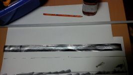
Ooooooh yeah, i finally got a aluminium etch to work.
i used tape on common household foil 10 micron thick to make a flexible laminate. i then dumped it in the etching tank for few seconds.
it then removed it and cleaned it with alcohol. taped it to a plain paper. ran it to my solid ink printer.
i diluted my etch acid allot still do use hydrogen peroxide + hydrochloric acid. so it takes a bit longer but finally my wax print does not come lose. look at tyhe pictures this is beter then i could even dream of. that small line is 1.1mm wide. love it 🙂 i am pretty stoked
Attachments
Ooooooh yeah, i finally got a aluminium etch to work.
i used tape on common household foil 10 micron thick to make a flexible laminate. i then dumped it in the etching tank for few seconds.
it then removed it and cleaned it with alcohol. taped it to a plain paper. ran it to my solid ink printer.
i diluted my etch acid allot still do use hydrogen peroxide + hydrochloric acid. so it takes a bit longer but finally my wax print does not come lose. look at tyhe pictures this is beter then i could even dream of. that small line is 1.1mm wide. love it 🙂 i am pretty stoked
Hello my friend,
This is impressive.
Keeps up the good work.
I havent got time to sow my results..
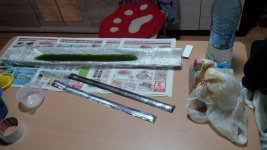
Here is some work in progress:
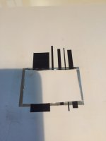
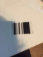
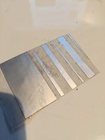
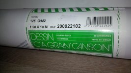
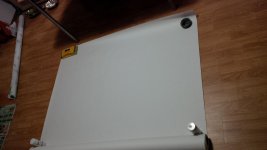
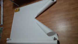
1) first two pics represents the paper that i told you about: the canson 120gr/sqm paper;
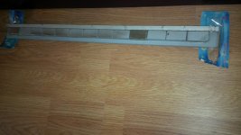
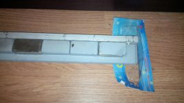
2) the second two pics represents the chopped magnet that i told you about;
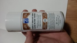
3) fifth: the laqueur that i told you that i want to use to spray it at the finals for humidity resistance;
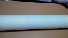
4) last pics: some work in progress;
I also found that its almost impossible to wind the coil; i didnt found a feasible and fast method to wind them..
Wrine have you found a method for winding this oval coil with copper wire?
Can someone recomend a solution for this problem (winding with copper wire)?
As you, Wrine, i found that i could cut the coil after i laquer the paper with two coats a thin aluminium cooking (a ordinary cooking foil) foil. After this it is very easy to remove the freshly cutted excess traces from the coil. BUT this takes allot of time.
I want to try the FeCl3 that we all use on pcb etching as you recomended. I also think that this way things will get easyer.
Thanks for posting.
Cheers
Sergiu
Here is some work in progress:
1) first two pics represents the paper that i told you about: the canson 120gr/sqm paper;
2) the second two pics represents the chopped magnet that i told you about;
3) fifth: the laqueur that i told you that i want to use to spray it at the finals for humidity resistance;
4) last pics: some work in progress;
I also found that its almost impossible to wind the coil; i didnt found a feasible and fast method to wind them..
Wrine have you found a method for winding this oval coil with copper wire?
Can someone recomend a solution for this problem (winding with copper wire)?
As you, Wrine, i found that i could cut the coil after i laquer the paper with two coats a thin aluminium cooking (a ordinary cooking foil) foil. After this it is very easy to remove the freshly cutted excess traces from the coil. BUT this takes allot of time.
I want to try the FeCl3 that we all use on pcb etching as you recomended. I also think that this way things will get easyer.
Thanks for posting.
Cheers
Sergiu
Attachments
-
 IMG_20151120_235736.jpg537.5 KB · Views: 433
 -
 IMG_20151120_235805.jpg558.5 KB · Views: 408
 -
 IMG_20151121_131210.jpg577.4 KB · Views: 234
 -
 IMG_20151121_131203.jpg415.3 KB · Views: 236
 -
 IMG_20151202_180122.jpg408.9 KB · Views: 213
 -
 IMG_20151202_181631.jpg436 KB · Views: 182
 -
 IMG_20151202_182709.jpg478.1 KB · Views: 202
 -
 IMG_20151202_181620.jpg514.3 KB · Views: 214
I havent got time to sow my results..
Here is some work in progress:
1) first two pics represents the paper that i told you about: the canson 120gr/sqm paper;
2) the second two pics represents the chopped magnet that i told you about;
3) fifth: the laqueur that i told you that i want to use to spray it at the finals for humidity resistance;
4) last pics: some work in progress;
I also found that its almost impossible to wind the coil; i didnt found a feasible and fast method to wind them..
Wrine have you found a method for winding this oval coil with copper wire?
Can someone recomend a solution for this problem (winding with copper wire)?
As you, Wrine, i found that i could cut the coil after i laquer the paper with two coats a thin aluminium cooking (a ordinary cooking foil) foil. After this it is very easy to remove the freshly cutted excess traces from the coil. BUT this takes allot of time.
I want to try the FeCl3 that we all use on pcb etching as you recomended. I also think that this way things will get easyer.
Thanks for posting.
Cheers
Sergiu
1. aha when i give it another go ill try the paper.
2. magnets is not an issue i thing.
3. it does add some weight, but dont know if it does anyhting
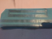
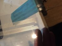
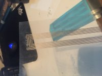
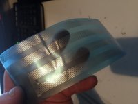
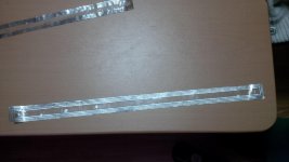
4. Coil winding sucks indeed. thats why i make etched coils. it gives me now as well the oportunity to use aluminium witch is nice. again lower weight. and to use it on thinner material like tape. or mylar. or directly onto the stuff used for membrane.(only possible if its not paper ofc). here a picture of glued foil to pvc transparant then etched. some lines came of due to my fast glueing of the al foil. but it should be possible. thats is a coil without a carrier. i do advice you to score a solid ink printer somewhere. you should be able to pick one up for les then 75 euro. look for xerox phaser line
and the blue foil is 7 micron alu on 7 micron mylar. lines where over etched. to agressive solution 🙁
i used Another less harmfull solution coppersulfate with salt.
Attachments
Last edited:
well still , my xerox solid ink is type 8500 and does not have the greatest DPI, 600 so it has some small problems with smaller spacing of 0.3 mm, still pretty decent but. etching makes it slightly more ragged. well atm no money for a 8550 or beter. this will have to do 🙂
ordered some new ink since it is bitching for new black ink for half a year. i also noticed some small striped in the ink, witch can be seen in the end result so maybe have to do some cleaning. and last but not least. tests showed that reheating the print seal the tiny holes that might be pressend in the wax ink. to much heat will smear the edges so dont overheat. or leave it as is. to bad you cant print twice onto the same material... it wont align and makes a mess of the ink already present. i can imagine the printer wont like that idea either 🙂
ordered some new ink since it is bitching for new black ink for half a year. i also noticed some small striped in the ink, witch can be seen in the end result so maybe have to do some cleaning. and last but not least. tests showed that reheating the print seal the tiny holes that might be pressend in the wax ink. to much heat will smear the edges so dont overheat. or leave it as is. to bad you cant print twice onto the same material... it wont align and makes a mess of the ink already present. i can imagine the printer wont like that idea either 🙂
well still , my xerox solid ink is type 8500 and does not have the greatest DPI, 600 so it has some small problems with smaller spacing of 0.3 mm, still pretty decent but. etching makes it slightly more ragged. well atm no money for a 8550 or beter. this will have to do 🙂
ordered some new ink since it is bitching for new black ink for half a year. i also noticed some small striped in the ink, witch can be seen in the end result so maybe have to do some cleaning. and last but not least. tests showed that reheating the print seal the tiny holes that might be pressend in the wax ink. to much heat will smear the edges so dont overheat. or leave it as is. to bad you cant print twice onto the same material... it wont align and makes a mess of the ink already present. i can imagine the printer wont like that idea either 🙂
Hi Wrine,
Nice progress.
I have given it a shot too. Look at the pics bellow.
It does need some finishing touches but I draw it with a permanent marker. I have to make some tests with the FeCl3 solution first to see if it doesnt etch all the coil. And another issue is how can I bond wires to the aluminium coil... I was thinking about taking the begining and the end of the coil outside of the cilinders and stick it to some screw joints but would it be possible to rip outside? 🙁
Do you know any sollution for this issue Wrine?
Cheers
Sergiu
Attachments
1 before you start. do rub the alumnium with some steel wool or anything it has to be really clean. use alcholol to clean after.
yeah problems with connection i thought of as wel. i though about coperplating the connection point. not sure in wich solution , normaly in the one i usse now, but since its eating my alumnium already i must either make it really weak or get something else
yeah problems with connection i thought of as wel. i though about coperplating the connection point. not sure in wich solution , normaly in the one i usse now, but since its eating my alumnium already i must either make it really weak or get something else
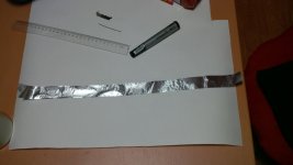
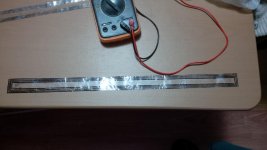
Hello my friend Wrine,
I have made some progress so far. In the pics bellow you can see the first "almost good" coil from almost 10. The FeCl3 is very dangerous and REALLY fast. It disipates allot of heat and toxic gases so you have to keep the windows open when doing this. I had to dillute the FeCl3 to aprox 1:3 with water. The coil has 3.9 ohms so this means the dims are good.
I think this solution is good if you have a steady hand a good permanent marker.
I have to do some more tests. I still dont know how to make some joints to the aluminium coil.
Cheers
Sergiu
Attachments
Nice!! Looking good , you might want to try etching with salt and copper sulfate no gasses and not that toxic. 🙂
Oh yeah connection is a huge problem tried copper plating buy ofc to plate aluminum is very difficult and involved way more the I thought it would 🙁
Oh yeah connection is a huge problem tried copper plating buy ofc to plate aluminum is very difficult and involved way more the I thought it would 🙁
Hello again my friend,
Here is what i found lately. It seems that there is a solution for this issue:https://www.youtube.com/watch?v=_mYkM9lHMho
(i think that this is very easy, especially when you use enameled copper wire for making leads to the coil)
and
https://www.youtube.com/watch?v=9iwawTk9gXI
( maybe you have a source for this AlumSolder because i dont)
I think i will try the first solution first... 😉
It seems that there was an elegant sollution for this issue right bellow our noses. 😀
I'm still searching for a solution to elegantly print a coil or a very resistant paint or marker for my coils..
Cheers
Sergiu
The very elegant solution for printing I gave you 🙂 get a Xerox phaser solid ink printer. Nice YouTube vid by the way I did not know this trick !!!for a rubanoid ithis this might be useful but when your backing off foil is some sort of plastic ( not kapton) this heat is gone bra problem . Button could easy get kapton tape an tape it to Au foil of choice print it etch it and use this trick for the connection
I was digging in another solution witch should be useful for all materials substrat. Using chemical plate Ali with tin. I mailed my chemicals about there liquid tin an they told Meir should plate aluminum as well. The tin should be able to be soldered 🙂 I think a bit more elegant option but not tested yet so time will telli might buy a can of the stuff. You could also plate the whole foil something I think they do in pro kapton/Alu laminates used in ribbons and such
I was digging in another solution witch should be useful for all materials substrat. Using chemical plate Ali with tin. I mailed my chemicals about there liquid tin an they told Meir should plate aluminum as well. The tin should be able to be soldered 🙂 I think a bit more elegant option but not tested yet so time will telli might buy a can of the stuff. You could also plate the whole foil something I think they do in pro kapton/Alu laminates used in ribbons and such
- Home
- Loudspeakers
- Planars & Exotics
- A DIY Ribbon Speaker of a different Kind