REW version 5.13, beta 3 is what I use for that 🙂. It has that new smoothing added based obviously on psychoacoustic principles. For a long time there were requests to add something like this to REW. Mitchba clued us in on that beta release on another thread: http://www.diyaudio.com/forums/full-range/273971-group-delay-questions-analysis-39.html#post4355384
In that other thread, the one about Jim's awesome room, we sort of concluded it's 1/24 oct smoothing with dips filled in. It's supposed to be a bit like the windowing used in Acourate. So it's a sliding window with a relative short window at high frequencies, growing gradually longer at lower frequencies. Basically trying to mimic how we hear.
From Mitch I learned that the Acourate windowing is still a bit different. I wouldn't know, I can't afford it 😀.
Here's the impulse/STEP in one plot:
A Linkwitz Riley 4th order would do just that, a 360 degree phase wrap, right?
Yes, that's correct. If the 2 drivers are timed properly for the listening axis, the phase on that axis would rollup smoothly over the entire XO range just as shown in all the IIR filter design books. The GD would also smoothly rollup over that range. The observation here was that this did not happen with my trial. There was what appeared to be a much faster/sharper/non-contiguous change.
Though you did mention the crossover at 100 Hz is somewhat different, asymmetrical and more steep. It would still cause delay.
Yes. The additional filters in that XO more closely approximate an acoustic LR-36 than an LR-24. This brings more phase rotation and that is reflected in the rePhase correction filter I use.
I understood the rest of your post to indicate that your setup also had this irregularity and that you have now found a control parameter that can eliminate that effect. If this is a correct understanding then I think we are on the same page now. I will keep this in mind as I try DRC again.
------------
More rambling regarding phase tracking: If the phase crosses a the XO then I would think the size and stability of the central lobe would be smaller and there would thus be more irregularity of the sound distribution in the room. This may have no impact to sound quality at the 100Hz XO frequency. SPL is said to rule with such large wavelengths. So eliminating a phase shift of 10ms may have not have any sonic impact. That said, I have experimented with timing that changes the 100Hz timing by 1/2 WL (with SW polarity reversed) and by 1 WL and it did seem pretty clear to me there was a very noticeable difference even though the measured SPL was identical. So at least in some situations this may be significant. This was done without using to the any phase correction filter of course. I hesitate to mention it, but under in my room I actually preferred the setting with the SW leading the Mains by 1 WL. Regardless, I continue to pursue idealized measurements rather than chasing subjective listening experiences.
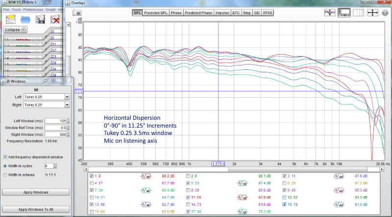
Phase tracking is probably more important at my 2k XO. I'm thinking it has increase the size of the sweet spot in my listening area and improve the soundstage and imaging. Below is recent test of my horizontal sound dispersion at 24". [I moved the mic as I was unwilling to move the speaker.]

I understood the rest of your post to indicate that your setup also had this irregularity and that you have now found a control parameter that can eliminate that effect. If this is a correct understanding then I think we are on the same page now. I will keep this in mind as I try DRC again.
More rambling regarding phase tracking: If the phase crosses a the XO then I would think the size and stability of the central lobe would be smaller and there would thus be more irregularity of the sound distribution in the room. This may have no impact to sound quality at the 100Hz XO frequency. SPL is said to rule with such large wavelengths. So eliminating a phase shift of 10ms may have not have any sonic impact. That said, I have experimented with timing that changes the 100Hz timing by 1/2 WL (with SW polarity reversed) and by 1 WL and it did seem pretty clear to me there was a very noticeable difference even though the measured SPL was identical. So at least in some situations this may be significant. This was done without using to the any phase correction filter of course. I hesitate to mention it, but under in my room I actually preferred the setting with the SW leading the Mains by 1 WL. Regardless, I continue to pursue idealized measurements rather than chasing subjective listening experiences.
The above is about correct. Yesterday after I wrote the reply for you about minimum phase and excess phase windows I figured why not try and play with the excess window size. If I remember correctly Audiolense lets you set the window length for phase manipulation and default was about half the length of the EQ window at low frequency. So that's what I tried and it did work to clean up the phase at the measurement position. To early for me to tell if it is an advancement. I need to see what it does off axis and I need some rebalance of my target. So far it does sound different, but certainly not in a bad way.
After a measurement session I'll be able to see what else is at play here.
Basically the phase looks similar to what you would get after correcting it with RePhase.
I'm still gonna try and get there (step by step) with less processing as I do believe the less processing needed, the better it gets. Processing isn't "THE" answer for me. But as seen it does/can help 😉. It's no real substitute for room treatment etc. at least, that's not how I look at it.
I'm still gonna try and get there (step by step) with less processing as I do believe the less processing needed, the better it gets. Processing isn't "THE" answer for me. But as seen it does/can help 😉. It's no real substitute for room treatment etc. at least, that's not how I look at it.
Yes, that was Kindhornman's point to a large extent I think. I hesitated to show how big my room problem is in the 100-600 range, but it is informative to do so. It shows up best on the new REW wavelet chart below, but can also be easily seen on the REW spectrograph as well. No signal EQ can do anything to help the direct sound nulls. The big questions are; is it better to Apply EQ get the SPL of some of the frequencies near the overall level of other frequencies even when it is arriving 20 ms late, or is it better to not EQ and have a large dip in the response at several of those mid frequencies? Possibly the answer is that; it depends on how the EQ is implemented (FIR vs IIR) and how much of the SPL dip is removed. This is my current interest - what EQ scheme to use and how much to apply.
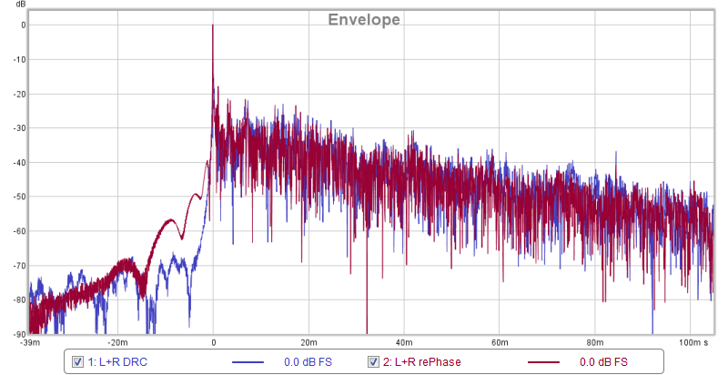
w/DRC

w/Rephase

That is indeed kind of scary looking... but I'd say you are not the only one getting something like this in a real live room.
For me it was kind of a revelation to be able to take a peak in a well damped room. If you look in the thread I linked for BYRTT (the one with REW 5.13), you'll find some measurements from jim1961 with a pair of Troels speakers (if they are still up of coarse). That room is excellent and gave me the opportunity to see what something like that actually looks like. No way processing is going to get you such results in a live room! Follow the link to his room on one of the early pages, it really is a work of art.
But the most important part is trying to figure out what we're looking at.
What I try to do is measure while having a damping panel I can place behind, above, below or where ever needed to find out in what direction I need to look for improvement.
I do have some damping panels placed and it is a big help! Sadly I cannot place more without upsetting my spouse. One panel is visible, as a piece of art, the remaining two are hidden behind curtains.

The visible panel behind the listening position, wall is much to close so I had to do something...
The panel is a DIY damping panel I had printed at Spoonflower, using their Kona fabric.
I found the base picture for this poster online in reasonable size and I made it mimic a very old original poster I had.
Probably not every one's cup of tea but I like it. Here's a bad picture of my original poster

You could say I "Remastered" my old poster 🙂. But chose not to do the color scheme of the current remasters.
I deliberately chose the line array to get rid of the biggest reflections from floor and ceiling. But line arrays have other things to worry about 🙂.
What can, or are you willing to do? As you said, it's all part of your home cinema as well as stereo, so I get it if your hands are somewhat tied in building an active FIR based system. That's not going to work easily without a PC running as Home Theatre setup.
Can you do any panels at all? 200 to 400 Hz is a relative easy target for glass fibre filled panels. First I'd look what's causing that dip at 200 and 400.
I have one at 130 and a lower at 70 but the above processing totally eliminates both. I still want to find out if the dip at 130 has something to do with the enclosure/drivers resonance frequency. If I can fight it there, I could get by needing less processing.
For me it was kind of a revelation to be able to take a peak in a well damped room. If you look in the thread I linked for BYRTT (the one with REW 5.13), you'll find some measurements from jim1961 with a pair of Troels speakers (if they are still up of coarse). That room is excellent and gave me the opportunity to see what something like that actually looks like. No way processing is going to get you such results in a live room! Follow the link to his room on one of the early pages, it really is a work of art.
But the most important part is trying to figure out what we're looking at.
What I try to do is measure while having a damping panel I can place behind, above, below or where ever needed to find out in what direction I need to look for improvement.
I do have some damping panels placed and it is a big help! Sadly I cannot place more without upsetting my spouse. One panel is visible, as a piece of art, the remaining two are hidden behind curtains.
The visible panel behind the listening position, wall is much to close so I had to do something...
The panel is a DIY damping panel I had printed at Spoonflower, using their Kona fabric.
I found the base picture for this poster online in reasonable size and I made it mimic a very old original poster I had.
Probably not every one's cup of tea but I like it. Here's a bad picture of my original poster
You could say I "Remastered" my old poster 🙂. But chose not to do the color scheme of the current remasters.
I deliberately chose the line array to get rid of the biggest reflections from floor and ceiling. But line arrays have other things to worry about 🙂.
What can, or are you willing to do? As you said, it's all part of your home cinema as well as stereo, so I get it if your hands are somewhat tied in building an active FIR based system. That's not going to work easily without a PC running as Home Theatre setup.
Can you do any panels at all? 200 to 400 Hz is a relative easy target for glass fibre filled panels. First I'd look what's causing that dip at 200 and 400.
I have one at 130 and a lower at 70 but the above processing totally eliminates both. I still want to find out if the dip at 130 has something to do with the enclosure/drivers resonance frequency. If I can fight it there, I could get by needing less processing.
Last edited:
I'm not willing to do more acoustically than I already have. I have not been able to identify the source of the big 400Hz dip. I actually don't think it is a reflection. There is no evidence of a strong reflection in the ETC. I am guessing it is combination of room modes. 400Hz is normally too high for room modes so that is questionable. Nonetheless, I suspect the issue is that the mains are too close to the center of the rooms 41" length. If that is it, then there is nothing I can do at this time other than the current effort to optimize the EQ for the situation.
I have had success analyzing reflections and mitigating them, but room mode analysis procedure an undeveloped skill for me. I don't no idea how to rule that in or out via measurements.
I have had success analyzing reflections and mitigating them, but room mode analysis procedure an undeveloped skill for me. I don't no idea how to rule that in or out via measurements.
I think you said you didn't want to move your speakers but a simple test would be to take one outside and see if you still have this hole in the FR if you are away from any reflective surfaces. If you move the microphone close to the speaker what happens to the curve with a very short window to remove the room from the equation.
I agree... at least make sure you're not chasing a null that's originating in the speaker itself.
I'd also do an impedance sweep of the speaker just to check nothing funny is happening there.
I'd also do an impedance sweep of the speaker just to check nothing funny is happening there.
I'm not willing to do more acoustically than I already have. I have not been able to identify the source of the big 400Hz dip. I actually don't think it is a reflection. There is no evidence of a strong reflection in the ETC. I am guessing it is combination of room modes. 400Hz is normally too high for room modes so that is questionable. Nonetheless, I suspect the issue is that the mains are too close to the center of the rooms 41" length. If that is it, then there is nothing I can do at this time other than the current effort to optimize the EQ for the situation.
I have had success analyzing reflections and mitigating them, but room mode analysis procedure an undeveloped skill for me. I don't no idea how to rule that in or out via measurements.
Room modes/reflections are exactly what you are most likely to be looking at; if not then gross speaker misalignment. Depth of 400Hz notch is in realm of wrong driver polarity as though seeking a null measurement for 400Hz crossover. Information about speaker and microphone placement relative to room boundaries and of microphone distance to each driver all need to be known.
I prefer spectrogram with various sized windows for showing horizontal lines indicative of room reflections.
The above graph would indicate it's not a reflection from a wall but could still be floor or ceiling due to the moving mic while the notch pretty much stays at the same spot. Either that or a room mode. But it would be wise to know what the speaker does by itself. I'd experiment by lifting the speaker up and (temporary) moving it about in a measurement session if you can't/won't take it outside.
Thanks for the thoughts and encouragement. I'm am also believing that, as you point out, this due reflections not modes. The mode thing was more just expressing frustration that I hadn't been able to identify a reflection problem.
After much effort I had given up on this and just accepted that I couldn't identify the cause. It's been long enough and my memory is poor as to what all I investigated at the time. With your comments I am now motivated to try again. I just now reviewed some old work and also did some new measurements. Maybe with your help I can make some progress.
I confirmed some basics regarding the Right MW:
> The MW response is smooth through the operating range per 1cm mic distance (see attachment)
> This not a Floor/Ceiling bounce. LP Calc = 536/146 Actual = depends if FDW is applied. With a small number the null is very deep at 400 with no FDW there is a double dip at 380 and 486.
> The coffee table in the picture (Post 89) provides no significant impact to the result (not shown), i.e., removed, covered with pillow and blanket, or bare glass.
> Previously I added to the poly fill of the box 2 times to see if that would impact the results - no effect. It is now judge it is at a max density, i.e., probably beyond optimal.
Post 89 also has a photo to give some idea of the speaker/room reflection points.
The legend provides mic distances for the measurements. One chart is with 1/6 smoothing and other add FDW = 5 cycles


Any thought as to what can be done to identify the cause?
After much effort I had given up on this and just accepted that I couldn't identify the cause. It's been long enough and my memory is poor as to what all I investigated at the time. With your comments I am now motivated to try again. I just now reviewed some old work and also did some new measurements. Maybe with your help I can make some progress.
I confirmed some basics regarding the Right MW:
> The MW response is smooth through the operating range per 1cm mic distance (see attachment)
> This not a Floor/Ceiling bounce. LP Calc = 536/146 Actual = depends if FDW is applied. With a small number the null is very deep at 400 with no FDW there is a double dip at 380 and 486.
> The coffee table in the picture (Post 89) provides no significant impact to the result (not shown), i.e., removed, covered with pillow and blanket, or bare glass.
> Previously I added to the poly fill of the box 2 times to see if that would impact the results - no effect. It is now judge it is at a max density, i.e., probably beyond optimal.
Post 89 also has a photo to give some idea of the speaker/room reflection points.
The legend provides mic distances for the measurements. One chart is with 1/6 smoothing and other add FDW = 5 cycles
Any thought as to what can be done to identify the cause?
If that was directed at me, I've got to think about it some more. The Spectogram you posted, was that with FDW as well? Never seen it look like that. I'm first trying to figure out why that dip at 400 is that strong in a L + R measurement. It would be good to see a spectrogram from each separate speaker, just to see where the null is landing.
You can limit it to the first 10 ms or less. I usually play with the controls (Window) to see if I can figure out when the dip starts to form itself. For instance, if you limit the time to about one cycle at that frequency, can you see the region of interest falling behind in SPL?
You can limit it to the first 10 ms or less. I usually play with the controls (Window) to see if I can figure out when the dip starts to form itself. For instance, if you limit the time to about one cycle at that frequency, can you see the region of interest falling behind in SPL?
The above graph would indicate it's not a reflection from a wall but could still be floor or ceiling due to the moving mic while the notch pretty much stays at the same spot. Either that or a room mode. But it would be wise to know what the speaker does by itself. I'd experiment by lifting the speaker up and (temporary) moving it about in a measurement session if you can't/won't take it outside.
Tis chart was with mic at only 24" just to show the dispersion and that there were not any off angle problems as a result of poor timing of the 2k XO.
I just ignored the dip at 400Hz to be from another source. Possibly my PEQ or possibly floor/ceiling bounce. The geometry is completely different from the listening position situation so it would not share an common reflection problem.
Regarding floor bounce; the mic is at 24" distance and 34" high. The MW 30.5" high so the cancelation freq is 152Hz. The ceiling cancelation is 60Hz. My PEQ does not have an filter in this area so that is not the cause either. This is another puzzle for me. I don't see how the dip at the listening position and this dip could be related to each other, but I also don't understand the cause of either.
My bad, I figured they were related... I'd still suggest measuring again at LP and raise speaker and remeasure.
One side at the time to research what happens/changes. Only change a single thing between measurements.
I noticed you cross the speakers in front of the listening position. So focus on single speaker measurements first to see what happens where. After that a combined result is interesting to watch.
One side at the time to research what happens/changes. Only change a single thing between measurements.
I noticed you cross the speakers in front of the listening position. So focus on single speaker measurements first to see what happens where. After that a combined result is interesting to watch.
Last edited:
If that was directed at me, I've got to think about it some more. The Spectogram you posted, was that with FDW as well? Never seen it look like that. I'm first trying to figure out why that dip at 400 is that strong in a L + R measurement. It would be good to see a spectrogram from each separate speaker, just to see where the null is landing.
You can limit it to the first 10 ms or less. I usually play with the controls (Window) to see if I can figure out when the dip starts to form itself. For instance, if you limit the time to about one cycle at that frequency, can you see the region of interest falling behind in SPL?
Those 2 charts are not the normal spectrograms, they are using REW's new Wavelet spectrogram. It's just out in beta release FDW was not applied. I looked at the right and left separately and while they are different than have similar problems. I usually 90% of my analysis is on separate speakers I only did L+R as the info in the thread did that. Attached is the DRC Left and Right channel Wavelets with 1/6 smoothing and a 30ms window.
Left

Right

Room modes/reflections are exactly what you are most likely to be looking at; if not then gross speaker misalignment. Depth of 400Hz notch is in realm of wrong driver polarity as though seeking a null measurement for 400Hz crossover. Information about speaker and microphone placement relative to room boundaries and of microphone distance to each driver all need to be known.
I prefer spectrogram with various sized windows for showing horizontal lines indicative of room reflections.
400HZ is mid band-pass for the MW here. The XO are steep and the SWs and TWs are more than 50dB down so they are not involved.
I augmented my sketch in Post 89 to show the speaker locations. The actual height to the Front L and R MW drivers is 30.5" (table shows 34", but that is the midpoint between MW and TW centers).

I have previously looked at spectrograms with various size windows after seeing some of you posts long ago. They basically show the same things in the midrange area as the wavelet chart. dips and nulls with some late arriving SPL at a result of my EQ settings. I could post a few if you think the might be informative. I can attach the REW files if you want to see those.
Reflections are root of modal behavior in listening rooms.
I'm not sure what to make of this. My understanding currently doesn't go beyond basic concepts of; LF modes, first reflections for wall, floor and ceiling bounces.
Are we back to where I thought I was, i.e., nothing can be done unless speakers are relocated, LP is moved, and/or significant room treatments added? If so, is it best to think of this as a reflection, mode, or maybe just room effect?
Edit:
I noticed a typo on the FR 'X' dimension in Post 117. It should read 275" not 175". Just in case you are planning to do an analysis with the dimensions.
Last edited:
Don't forget things close to the microphone can reflect back to it... a dip at ~400 Hz cannot be that far away, either from the speaker or the mic. I don't think that will be a room mode. I'd still lift the speakers to see what happens, or the microphone to find the other dip that they seem to share. Seeing that the distance to floor is what they have in common... nothing else seems to be equal distance to both speakers.
If that first peak above -20 dB is at 2.5 ms I'd say that's the one bugging you at ~400 Hz. A bit hard to tell on this graph though. I suspect it's something close to the mic, not the speakers. The mic will be quite good at listening from behind. Are the chairs we see in your room picture there when the mic is placed during a measurement?
Don't give up, I never give up, let it slide for a couple of days if you can't get it immediately. Think about it and it will come to you. Don't get hung up with calculators, experiment in the real world. The dip at ~400 is not exactly the same, left and right, but it's early enough to be close to speakers or mic.
The other one at ~200 Hz seems equal to both sides, so it's something they have in common. So make a measurement with them and break up the things they have in common, like distance to floor etc. Look around you and you'll find clues/suspects. Your filtered IR looks about the same as mine, except for that fist peak above -20 dB. It's got to be close and needs a bit of fixing. If it's from behind the mic position you only need to fix it while measuring. The mic will be way better at picking it up than you will be. A couple of pillows might be all it takes to get rid of that one. If there's a lady in the house there have got to be pillows nearby right? 😀
Last edited:
I wonder if the dip could possibly be related to the speaker stands. I have a very early spike in my listening position measurements that I have been thinking could be related to the stands since they are not yet mass loaded/damped.
- Home
- Loudspeakers
- Full Range
- A convolution based alternative to electrical loudspeaker correction networks