In my setup I use a Pre-pro to 2 DCX2496 units for XO management and EQ to 5 DIY 2-way mains and 2 SWs (12 drivers/channels).
For music I use the pre-pro DLNA feature to tap a remote PC containing my music files. The Foobar convolution feature is implemented there at the remote PC. The DRC filter thus only impacts the stereo music sent from the server. I still want some 5.1 PEQ to help with the other sources.
Sorry to jump into this forum given my inappropriate system setup, but this thread has helped me get started in my desire to evaluate the merits of DRC for music. I couldn't resist.")
For music I use the pre-pro DLNA feature to tap a remote PC containing my music files. The Foobar convolution feature is implemented there at the remote PC. The DRC filter thus only impacts the stereo music sent from the server. I still want some 5.1 PEQ to help with the other sources.
Sorry to jump into this forum given my inappropriate system setup, but this thread has helped me get started in my desire to evaluate the merits of DRC for music. I couldn't resist.
jtalden,
It just goes to show that you can't always correct for room response by manipulation on the electronics side of things. You can actually make things worse at times taking that approach. Correcting room problems can be just as important as trying to correct electronically a problem that has nothing to do with the electronics or speaker response. A hard lesson to learn for many.
It just goes to show that you can't always correct for room response by manipulation on the electronics side of things. You can actually make things worse at times taking that approach. Correcting room problems can be just as important as trying to correct electronically a problem that has nothing to do with the electronics or speaker response. A hard lesson to learn for many.
Yes, I would need to make changes to the room, acoustic treatments, speaker positions and/or listening position to address the fundamental causes of some of my biggest issues.
While we can make things worse with EQ it seems we apparently can also make them better in many cases, even in the range above the Schroeder frequency. So the dilemma for me is to create as much EQ help as possible given my current room and setup limitations as I am unwilling to change those things at this time. Is this approach consistent with your approach?
There is a camp that feels that room influences cannot be improve at all above the Schroeder frequency via EQ. Most speaker designers seem to be in this camp, i.e., EQ the speakers to have a flat anechoic response at the design stage and only EQ the room below the Schroeder frequency. Maybe apply a little shaping to a house curve.
I personally don't have an overly strong opinion, but tend to think that all the rave reviews of room correction software must have some merit. The benefit probably varies widely though based on the particular situation and EQ scheme used.
This trial was very aggressive EQ setup with DRC adding about +7dB in the same 300-400Hz range where my PEQ already applied +5dB. I can't say the it caused a obvious sound quality problem for me. Maybe if my hearing was more at normal levels...
jtalden,
There are as many opinions on this as everything else in audio. A lot has to do with the dispersion pattern of the speakers in a room above the Schroeder frequency. A more directional speaker is going to interact a lot different than an OB speaker or Omni than a horn loaded system. I know some designers will say you cause as many problems as you solve with FIR and IIR filters if the filter lengths become long. Now add in some video you have to sync to and it becomes a huge problem. I say use whatever you are doing judiciously, the minimum manipulations is often the best sounding.
There are as many opinions on this as everything else in audio. A lot has to do with the dispersion pattern of the speakers in a room above the Schroeder frequency. A more directional speaker is going to interact a lot different than an OB speaker or Omni than a horn loaded system. I know some designers will say you cause as many problems as you solve with FIR and IIR filters if the filter lengths become long. Now add in some video you have to sync to and it becomes a huge problem. I say use whatever you are doing judiciously, the minimum manipulations is often the best sounding.
I expected a bit more from the DRC STEP results, however I'm not using a 4 cycle correction like the one in Greg's tool set. I use a longer window at high frequencies and also at low frequencies after several tests to see if I could find the limits where things start to sound unnatural. In the midrange this point is easily reached and the correction window I use there isn't longer than the 4 cycle window. I do need a bit more at high frequencies to correct my line array highs. Not surprising as it is a bit time smeared by all the different speakers arriving one after the other at the mic position.
Here's my SR:

I have a window of about 9 cycles of correction at low frequencies, tapering to 4 cycles in the mids and about 11 cycles at the highest frequency. But I have to make a note that line arrays are a different animal than most speakers.
In my setup I do have delay too, at lower frequencies, starting around the resonant frequency of the enclosure, still working on that.
I noticed your 10 ms delay, that's why I asked about your room and speakers.
A longer correction window could get rid of that, but is not the solution i.m.h.o. It will probably start to sound unnatural and the sweet spot will be very small. So I try to resolve what I can by other means. I did play with RePhase but didn't want to loose the nice frequency response I got with DRC.
I'm still a bit puzzled with your DRC step. More information on room and speakers might help here. Any crossovers at play?
I also use a bit of EQ first but did limit that to broad strokes for DRC. I found it more pleasing that way. I use no high Q PEQ filters in IIR.
Room treatment does definitely help get better results. The above STEP from me is with minimum phase FIR correction, not linear phase.
About the video sync, no problem for me as I use JRiver to play audio and movies. Lot's of ways to get both in sync and the convolution engine in JRiver automatically does compensation for video/audio sync for the convolution.
In my opinion FIR filtering with a windowed correction gets me better results than pure IIR filtering and takes away a lot of the problems Kindhornman is mentioning. In reality you're actually only equalizing the direct speaker response with the short windows used at mid frequencies and up. As long as your first reflection points are treated/damped. Something that's mentioned in the DRC guide.
Here's my SR:
I have a window of about 9 cycles of correction at low frequencies, tapering to 4 cycles in the mids and about 11 cycles at the highest frequency. But I have to make a note that line arrays are a different animal than most speakers.
In my setup I do have delay too, at lower frequencies, starting around the resonant frequency of the enclosure, still working on that.
I noticed your 10 ms delay, that's why I asked about your room and speakers.
A longer correction window could get rid of that, but is not the solution i.m.h.o. It will probably start to sound unnatural and the sweet spot will be very small. So I try to resolve what I can by other means. I did play with RePhase but didn't want to loose the nice frequency response I got with DRC.
I'm still a bit puzzled with your DRC step. More information on room and speakers might help here. Any crossovers at play?
I also use a bit of EQ first but did limit that to broad strokes for DRC. I found it more pleasing that way. I use no high Q PEQ filters in IIR.
Room treatment does definitely help get better results. The above STEP from me is with minimum phase FIR correction, not linear phase.
About the video sync, no problem for me as I use JRiver to play audio and movies. Lot's of ways to get both in sync and the convolution engine in JRiver automatically does compensation for video/audio sync for the convolution.
In my opinion FIR filtering with a windowed correction gets me better results than pure IIR filtering and takes away a lot of the problems Kindhornman is mentioning. In reality you're actually only equalizing the direct speaker response with the short windows used at mid frequencies and up. As long as your first reflection points are treated/damped. Something that's mentioned in the DRC guide.
Last edited:
I expected a bit more from the DRC STEP results, however I'm not using a 4 cycle correction like the one in Greg's tool set. I use a longer window at high frequencies and also at low frequencies after several tests to see if I could find the limits where things start to sound unnatural. In the midrange this point is easily reached and the correction window I use there isn't longer than the 4 cycle window. I do need a bit more at high frequencies to correct my line array highs. Not surprising as it is a bit time smeared by all the different speakers arriving one after the other at the mic position.
I have a window of about 9 cycles of correction at low frequencies, tapering to 4 cycles in the mids and about 11 cycles at the highest frequency. But I have to make a note that line arrays are a different animal than most speakers.
I intend to experiment some more with other settings. For now, I still have no understanding how to make the window adjustments for freq ranges as you refer to. Maybe I read over it and it didn't register. I will have to do more research to see if I can better understand the DRC controls and their impact. I do have a reasonable working understanding of the basic audio concepts including window concepts. If you have a hint or link that may help get me started with great, otherwise I will just have to go through thread and the DRC documentation again. I’m thinking possibly it’s necessary to build long script files like you posted and that I skimmed over? It seems there would be several stages of them and possibly they all somewhat different? There are numerous toggles to set correctly and that with the long script files is a bit overwhelming at this point. I can’t complain that there isn’t enough options to try; so many degrees of freedom! Anyway, you can see that I am still just getting started.
I noticed your 10 ms delay, that's why I asked about your room and speakers.
A longer correction window could get rid of that, but is not the solution i.m.h.o. It will probably start to sound unnatural and the sweet spot will be very small. So I try to resolve what I can by other means. I did play with RePhase but didn't want to loose the nice frequency response I got with DRC.
I'm still a bit puzzled with your DRC step. More information on room and speakers might help here. Any crossovers at play?
My DCX is providing IIR XO filters and delays such that there is very close phase tracking throughout both XOs down to maybe more than a -50dB level before starting to diverge. This results in a very stable frontal lobe and very smooth off axis response horizontally. Vertically I have the same lobeing issues that all 2-way bookshelf speakers have using 7"/1" drivers. The IR and ETC charts above shows I have reasonably controlled the first reflections. Some attachments below will help clarify my situation for you. The 2kHz XO approximates an acoustic LR-24. The 100Hz XO is steeper and a bit asymmetric. Filtering and delays were adjusted as needed in both XOs to achieve the target of close phase tracking for the direct sound. The measured phase tracking at the 100Hz XO at the listening position with a wide window is less than ideal as the modes there are disruptive. The SR with DRC was a question for me as well and thus I did not originally attach it. Possibly it is something in my current setup or a mistake in my implementation of the DRC process. I had several problems and had to backtrack several times. I will probably find the issue as I experiment more. I made a minor adjustment to my setup as a result of investigating the DRC SR issue. I will repeat the initial DRC filter trial so see if the SR changes and then try some modification to DRC the settings along the lines you referred to. This will take a while.
About the video sync, no problem for me as I use JRiver to play audio and movies. Lot's of ways to get both in sync and the convolution engine in JRiver automatically does compensation for video/audio sync for the convolution.
Baby steps - I'm not ready to build and install a local HTPC. There is the expense and also it is still beyond me to figure out inputs/outputs from several sources including DirectTV DVRs. It also would complicate the various audio experiments I enjoy doing. My current setup approaches the measurements of most DRC, Dirac, Acourate, installations I have seen posted and it sounds very good to me. However, that doesn’t impact the reason of this effort. If I find that DRC can provide significantly better stereo sound quality then I will be motivated to consider what it would take implement it more broadly in my system. If it is marginally better then I will probably just use it for music.
In my opinion FIR filtering with a windowed correction gets me better results than pure IIR filtering and takes away a lot of the problems Kindhornman is mentioning. In reality you're actually only equalizing the direct speaker response with the short windows used at mid frequencies and up. As long as your first reflection points are treated/damped. Something that's mentioned in the DRC guide.
Yep, the strong testimonials are the reason I want see for myself if it improves my particular setup. This first very rough trial hasn’t discouraged me at all. I will give it a fair shot.


jtalden, could you post a plot of the FR/phase with REW's new psychoacoustic smoothing?
And maybe the GD plot after using that smoothing? Just trying to get a peek at the first wave that hits your listening position.
Attached are the charts.
FYI, I neglected to show or mention or that the Phase and GD in Post 78 both included Frequency Dependent Windowing with a window of 4 cycles (if I remember correctly). They are good representation of the direct sound phase characteristic.


Thanks for the extra background info. I've written about variable windows before, let me look for it...
3 variables are at play here;
MPUpperwindow, setting the window length at 20 kHz
MPLowerWindow, setting the window length at 20 Hz and finally
MPWindowExponent, determining which curve to follow according to the above graph.
To make it easier for myself to experiment I use DRCDesigner, with that program I can change the 3 above parameters with sliders. But you'd have to know a little about how that GUI works to use it. It's not hard but it's important to know it always uses one template as the base for it's "Generate Custom Filters" tab, and that's the soft44100.drc (if you're using 44100 as sample rate).
As that soft44100.drc template I use a slightly modified version of the template from gmad. I'ts uploaded somewhere on this thread if you want to look at it.
I hope with the above I made it a bit clearer which settings determine the windowing. There is another windowing being applied for Excess phase. These are called:
EPUpperwindow, setting the window length at 20 kHz
EPLowerWindow, setting the window length at 20 Hz and finally
EPWindowExponent, determining which curve to follow according to the above graph.
I haven't experimented with different lengths of the Excess phase windows yet, I only set the EPWindowExponent to the same value of the MPWindowExponent. But DRCDesigner sets the EPUpperWindow and EPLowerWindow based on the MP window settings.
On the 10 ms delay, it seems the crossover is one cycle of delay behind for the low frequencies. That would fit the 10 ms at 100 Hz. In phase but one cycle late for all lower frequencies. A long window DRC correction (like the normal template 10 cycles) might correct that but like I said, it doesn't always sound the best (to me).
I bet the SR up higher is also a crossover issue that won't be solved/smoothed out with a 4 cycle correction.
You could run the 8 cycle template from gmad or the Normal template, just to look what it does for the SR. Not to listen too, although it doesn't hurt to know how that sounds.
Look at the above graph, it shows the windowing in the Normal template, which is 10 cycles. The green middle line (WE=1.0) shows the usual setting of MPWindowExponent=1.0. If we were to change the MPWindowExponent to 0.8 you'll see in the above graph that it makes no difference at 20 kHz or 20 Hz, but the window about halfway will be reduced. at 1000 Hz it will no longer be 10 ms (green line, WE=1.0) but less than 5 ms (light green line, WE=0.8). The template from gmad has WE= 1.0 and follows a straight line like in the graph above, but with a 4 cycle window length.
3 variables are at play here;
MPUpperwindow, setting the window length at 20 kHz
MPLowerWindow, setting the window length at 20 Hz and finally
MPWindowExponent, determining which curve to follow according to the above graph.
To make it easier for myself to experiment I use DRCDesigner, with that program I can change the 3 above parameters with sliders. But you'd have to know a little about how that GUI works to use it. It's not hard but it's important to know it always uses one template as the base for it's "Generate Custom Filters" tab, and that's the soft44100.drc (if you're using 44100 as sample rate).
As that soft44100.drc template I use a slightly modified version of the template from gmad. I'ts uploaded somewhere on this thread if you want to look at it.
I hope with the above I made it a bit clearer which settings determine the windowing. There is another windowing being applied for Excess phase. These are called:
EPUpperwindow, setting the window length at 20 kHz
EPLowerWindow, setting the window length at 20 Hz and finally
EPWindowExponent, determining which curve to follow according to the above graph.
I haven't experimented with different lengths of the Excess phase windows yet, I only set the EPWindowExponent to the same value of the MPWindowExponent. But DRCDesigner sets the EPUpperWindow and EPLowerWindow based on the MP window settings.
On the 10 ms delay, it seems the crossover is one cycle of delay behind for the low frequencies. That would fit the 10 ms at 100 Hz. In phase but one cycle late for all lower frequencies. A long window DRC correction (like the normal template 10 cycles) might correct that but like I said, it doesn't always sound the best (to me).
I bet the SR up higher is also a crossover issue that won't be solved/smoothed out with a 4 cycle correction.
You could run the 8 cycle template from gmad or the Normal template, just to look what it does for the SR. Not to listen too, although it doesn't hurt to know how that sounds.
Last edited:
Figuring out the settings for MPLowerWindow and MPUpperWindow is another matter.
When running DRC you get an info text rolling across the screen. That shows the actual windowing parameters from DRC. You'll notice these are half of what you set for MPLowerwindow and MPUpperwindow. Those numbers correspond with actual sample length for the windowing.
Here's the sample for the 10 cycle Normal template:
Notice 22050 (samples) at 20 Hz.
44100 / 20 Hz = 2205 * 10 cycles = 22050
Notice 22 (samples) at 20000 Hz
44100 / 20000 hz = 2.205 * 10 cycles = 22
In the Normal template that translates to:
MPLowerWindow = 44100 (22050 * 2) = 500 ms
MPUpperWindow = 44 (22 * 2) = 0.5 ms
So for a 4 cycle window length at 20 Hz you'd need:
44100 samples divided by 20 Hz = 2205 (samples in each cycle) * 4 = 8820 samples.
So if I set MPLowerwindow to 2 * 8820 = 17640 I'll have a 4 cycles window.
Same for 20000 Hz:
44100 / 20000 = 2.205 * 4 = 8.82 samples.
MPUpperwindow = 2 * 8.82 = 17.64, rounded up to 18
You'll notice those are the values used in gmad's template for the 4 cycle template.
The numbers for the 8 cycle template will be:
44100/20 * 8 * 2 = 35280
44100/20000 * 8 * 2 = 35 (rounded to closest integer)
Hope this makes sense, I'll try and rephrase if needed.
When running DRC you get an info text rolling across the screen. That shows the actual windowing parameters from DRC. You'll notice these are half of what you set for MPLowerwindow and MPUpperwindow. Those numbers correspond with actual sample length for the windowing.
Here's the sample for the 10 cycle Normal template:
Code:
Minimum phase component single side sliding lowpass prefiltering.
Input signal prewindowing.
R - Initial lowpass convolution...
R - Band:   0,    20.0 Hz, width:  22050, FIR, convolution...
R - Band:   1,    25.2 Hz, width:  17501, FIR, convolution...
R - Band:   2,    31.7 Hz, width:  13890, FIR, convolution...
R - Band:   3,    40.0 Hz, width:  11024, FIR, convolution...
R - Band:   4,    50.4 Hz, width:   8750, FIR, convolution...
R - Band:   5,    63.5 Hz, width:   6945, FIR, convolution...
R - Band:   6,    80.0 Hz, width:   5512, FIR, convolution...
R - Band:   7,   100.8 Hz, width:   4375, FIR, convolution...
R - Band:   8,   127.0 Hz, width:   3472, FIR, convolution...
R - Band:   9,   160.0 Hz, width:   2756, FIR, convolution...
R - Band:  10,   201.6 Hz, width:   2187, FIR, convolution...
R - Band:  11,   254.0 Hz, width:   1736, FIR, convolution...
R - Band:  12,   320.0 Hz, width:   1378, FIR, convolution...
R - Band:  13,   403.5 Hz, width:   1093, FIR, convolution...
R - Band:  14,   508.0 Hz, width:    868, FIR, convolution...
R - Band:  15,   640.0 Hz, width:    689, FIR, convolution...
R - Band:  16,   807.6 Hz, width:    546, FIR, convolution...
R - Band:  17,  1016.0 Hz, width:    434, FIR, convolution...
R - Band:  18,  1281.8 Hz, width:    344, FIR, convolution...
R - Band:  19,  1615.1 Hz, width:    273, FIR, convolution...
R - Band:  20,  2041.2 Hz, width:    216, FIR, convolution...
R - Band:  21,  2563.2 Hz, width:    172, FIR, convolution...
R - Band:  22,  3241.4 Hz, width:    136, FIR, convolution...
R - Band:  23,  4081.4 Hz, width:    108, FIR, convolution...
R - Band:  24,  5124.9 Hz, width:     86, FIR, convolution...
R - Band:  25,  6480.5 Hz, width:     68, FIR, convolution...
R - Band:  26,  8159.0 Hz, width:     54, FIR, convolution...
R - Band:  27, 10243.9 Hz, width:     43, FIR, convolution...
R - Band:  28, 12951.2 Hz, width:     34, FIR, convolution...
R - Band:  29, 16303.4 Hz, width:     27, FIR, convolution...
F - Band: 30, 20000.0 Hz, width: 22, FIR, completed.44100 / 20 Hz = 2205 * 10 cycles = 22050
Notice 22 (samples) at 20000 Hz
44100 / 20000 hz = 2.205 * 10 cycles = 22
In the Normal template that translates to:
MPLowerWindow = 44100 (22050 * 2) = 500 ms
MPUpperWindow = 44 (22 * 2) = 0.5 ms
So for a 4 cycle window length at 20 Hz you'd need:
44100 samples divided by 20 Hz = 2205 (samples in each cycle) * 4 = 8820 samples.
So if I set MPLowerwindow to 2 * 8820 = 17640 I'll have a 4 cycles window.
Same for 20000 Hz:
44100 / 20000 = 2.205 * 4 = 8.82 samples.
MPUpperwindow = 2 * 8.82 = 17.64, rounded up to 18
You'll notice those are the values used in gmad's template for the 4 cycle template.
The numbers for the 8 cycle template will be:
44100/20 * 8 * 2 = 35280
44100/20000 * 8 * 2 = 35 (rounded to closest integer)
Hope this makes sense, I'll try and rephrase if needed.
One more note on the SR: there is a setting in DRC to correct the phase to Linear phase instead of Minimum phase. Both Greg (gmad) and I have toyed with it without being overwhelmed with the results. The setting is: EPPFFlatType. in gmad (and my own) template this is set to M.
Setting that to L would in theory result in flatter phase (like you were doing in RePhase) given a long enough window.
Setting that to L would in theory result in flatter phase (like you were doing in RePhase) given a long enough window.
6.6.15 EPPFFlatType
This is the type of procedure adopted for the excess phase component renormalization. L means applying linear phase renormalization, M means applying minimum phase renormalization, D means applying another homomorphic deconvolution stage to extract just the excess phase component of the prefiltered excess phase component. L applies a linear phase filter that equalizes the excess phase amplitude response to flat, M means minimum phase, i.e. it uses a minimum phase filter to achieve the same result. The D procedure provides the same effect of the M procedure when EPPFOGainFactor is equal to 0. Any difference is just caused by numerical errors.
Regarding Post 91:
Window contours:
This was helpful. I understand the chart and think I understand that only the 3 variables need to be selected to chose the desired contour of the window function for both MP and EP stages.
Step Response:
Your suggesting that the 10ms offset may be due to my delay settings in the XO. The tracking charts I provided could indeed be consistent with this condition if the SW trace was shifted 360° in the REW chart I posted. I have been very careful however using both REW and HolmImpulse to assure this is not the case. I normally do not unwrap the phase to avoid this problem. With the phase wrapped and locked timing in REW and Holm I would expect to see the phase cross at a significant angle at the XO freq if the timing were off 1 WL (10ms). Also the initial rise of the SW IR would lag the initial rise of the MW IR. I didn't post any charts that show this above, but phase tracking is identical on a wrapped chart.
Regarding Post 92:
Thanks. I think I follow this 'MPLower...' and 'MPUpper...' calculation okay.
Regarding Post 92:
I left EPPFFlatType at M in the 5cycles-44.1.drc file I used. I don't feel a linear phase down to 20Hz is really necessary for sound quality. I only do it because I can and it does makes the measurements look more idealized and thus my analysis is easier. I will not worry about that part for now.
For now I will try a repeat to assure I get the same result and to get more comfortable with the process. If the strange GD offset is still there I try some other settings.
I'll also look at the normal-44.1.drc template you mention to see what the differences are.
I don't any other particular questions until do this.
Thanks again for all your help.
Step Response:
Your suggesting that the 10ms offset may be due to my delay settings in the XO. The tracking charts I provided could indeed be consistent with this condition if the SW trace was shifted 360° in the REW chart I posted. I have been very careful however using both REW and HolmImpulse to assure this is not the case. I normally do not unwrap the phase to avoid this problem. With the phase wrapped and locked timing in REW and Holm I would expect to see the phase cross at a significant angle at the XO freq if the timing were off 1 WL (10ms). Also the initial rise of the SW IR would lag the initial rise of the MW IR. I didn't post any charts that show this above, but phase tracking is identical on a wrapped chart.
A Linkwitz Riley 4th order would do just that, a 360 degree phase wrap, right?
Though you did mention the crossover at 100 Hz is somewhat different, asymmetrical and more steep. It would still cause delay.
I experimented a bit with DRC and the Excess phase parameters. Normally the Excess phase lower window would be very small compared to the minimum phase lower window. It is recommended to have EPUpperWindow the same as MPUpperWindow but for EPLowerWindow it is advised as MPLowerWindow divided by A (DRC documentation) With A being a value between 16 and 24.
I decided to experiment and set A to 2(!). That would make the Excess phase window half the length of the FR correction window. It did remove the phase turn I get between 100 and 200 Hz. But is also was less effective in obtaining a flatter FR response in that same area in my case. So the phase straightening isn't totally separate from the frequency response.
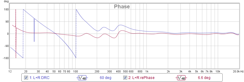
Here's my phase behavior as presented by REW's new psychoacoustic smoothing:

My usual settings with EPLowerWindow set to (MPLowerWindow/16) as outlined in the DRC documentation.
And this is the same smoothing with EPLowerWindow set to half of MPLowerWindow:

FR is better in the upper case, phase is more true to minimum phase except for maybe the dip/wiggle at 70 Hz (which is definitely due to my room) in the lower plot.
I've listened to both for a while, not sure which I prefer yet. Probably because the balance I usually have in the lower frequencies is a bit off. I did not measure the combined left/right response. We're looking at the predicted results here, not real measurements. Though usually the real measurements are not far off.
Last edited:
Just for fun, this is what the STEP looks like for the bigger Excess phase window if my target would be flat response:

(EPPFFlatType = M, PLType = M, PSFilterType = T)
And with a few settings to Linear phase instead of Minimum phase would give this:

(EPPFFlatType = L, PLType = L, PSFilterType = L)
(EPPFFlatType = M, PLType = M, PSFilterType = T)
And with a few settings to Linear phase instead of Minimum phase would give this:
(EPPFFlatType = L, PLType = L, PSFilterType = L)
Last edited:
Just for fun, this is what the STEP looks like for the bigger Excess phase window if my target would be flat response:
(EPPFFlatType = M, PLType = M, PSFilterType = T)
And with a few settings to Linear phase instead of Minimum phase would give this:
(EPPFFlatType = L, PLType = L, PSFilterType = L)
Holy cow it's beatifull i nearly can't breathe.
In above linear phase then hinted when looking at SR decay now is out to more than 12mSec verse ~7mSec below from post 87, where is f3 now landed. Post 87 below you also show a IR indicating bass boost target curve, would you share IR for the above linear phase plot
.Great thanks data and help guides, some day when time allows will dive into the magic.
The results of the linear phase attempt were even more surprising as the FR was back to flat also:

Again, REW Psychoacoustic smoothing, this time with minimum phase generated to compare. Still working with predicted results here... I'll try and measure it on Friday. Guess what convolution I'm listening to right now. The above linear phase correction with my preferred sloped response.
STEP with a bit wider view:

I'll send you a PM for the impulse. (edit: PM send)
In a way, this did exactly what I tried to get a few weeks ago with combining DRC and RePhase. I was unsuccessful in getting that right. Glad I tried this, triggered by the question from jtalden.
Again, REW Psychoacoustic smoothing, this time with minimum phase generated to compare. Still working with predicted results here... I'll try and measure it on Friday. Guess what convolution I'm listening to right now
. The above linear phase correction with my preferred sloped response. STEP with a bit wider view:
I'll send you a PM for the impulse. (edit: PM send)
In a way, this did exactly what I tried to get a few weeks ago with combining DRC and RePhase. I was unsuccessful in getting that right. Glad I tried this, triggered by the question from jtalden.
Last edited:

.....Again, REW Psychoacoustic smoothing, this time with minimum phase generated to compare. Still working with predicted results here... I'll try and measure it on Friday. Guess what convolution I'm listening to right now
.....
I'll send you a PM for the impulse. (edit: PM send)
In a way, this did exactly what I tried to get a few weeks ago with combining DRC and RePhase. I was unsuccessful in getting that right. Glad I tried this, triggered by the question from jtalden.
Now you shared FR and phase too have to say those plots are stunning and have begun look as artistic paintings in class with gmad and Barleywater.
Thanks PM, at moment quite busy and will write back tonight, in meantime have a laugh because by accident i requested share IR but in reality i meant if you would share IR plot on same paper as SR
.Regarding smoothing even if put my glasses on i can't find smooting in REW named "Psychoacoustic" and manual check for REW updates doesn't help either, my current version say "REW V5.12" is that wrong or too old.
My own two way FAST a 10F/8424 combined SPH-250KE is not bad and i give it at least half a year more with a arsenal of investigations ideas to extract the best of build, but has to say the more i think about a next step up config for future years it stands clear the route must be trace a NL masterpiece or go Synergy way. I could imagine going arrays road would win for decay time as Overkill Audio often recommend as very important verse a Synergy.
Back to job, have best listening session the linear phase correction added your preferred slope
.
Last edited:
- Home
- Loudspeakers
- Full Range
- A convolution based alternative to electrical loudspeaker correction networks