Here's a rough outline of my latest speaker correction method which mainly uses REW. The idea is to apply a (speaker) calibration file to an IR of your desired target response. It's about as non automated as it gets, but it's fun and can give really good results.
Create speaker calibration text file:
- Apply mic cal file and FDW of your choice to a minimum phase speaker measurement
- Export measurement as a text file (applying at least 1/48 oct. smoothing to the measurement prior to exporting will prevent the resulting file from being unnecessarily large)
Create filter text file:
- Load an Impulse response of your desired target into REW
- Apply speaker calibration file and at least 1/48 oct. smoothing
- Export as a text file
Convert filter text file to an impulse response:
- Prep filter text file for DRC (while optionally removing definition file points for unnecessarily low freqs)
- Load clean impulse into DRC sample folder (serving as the impulse response to be “corrected”)
- Set PSPointsFile to filter text file (choice of config file doesn’t really matter here)
- Run DRC to create an IR from the text file
The thing I really like about this is the ability to correct towards a target (like REW’s auto EQ) but with any level of resolution desired (DRC applies the target response “blindly” and I end up having to subsequently tune the bottom end with REW).
Here’s a tip for room correction: Try using psychoacoustic smoothing on top of a 1/24 octave FDW for the speaker cal file. This will prevent excessive dip correction and may result in a better magnitude response envelope (peaks of the FR forming a straight line). I’ve found this along with a 1 dB/oct. tilt above 1 kHz to work well.
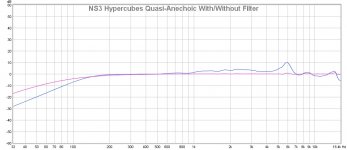
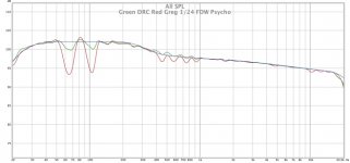
The first graph shows the responses of a quasi-anechoic freefield measurement with and without a filter derived from a 1/12 oct smoothed cal file and IR of an 80 Hz HP filter with a Q of 0.5. The second graph shows the responses of a room measurement with and without a filter derived from a psychoacoustically smoothed 1/24 oct freq dependent windowed cal file and IR of a 40 Hz HP filter with a Q of 0.5.
Create speaker calibration text file:
- Apply mic cal file and FDW of your choice to a minimum phase speaker measurement
- Export measurement as a text file (applying at least 1/48 oct. smoothing to the measurement prior to exporting will prevent the resulting file from being unnecessarily large)
Create filter text file:
- Load an Impulse response of your desired target into REW
- Apply speaker calibration file and at least 1/48 oct. smoothing
- Export as a text file
Convert filter text file to an impulse response:
- Prep filter text file for DRC (while optionally removing definition file points for unnecessarily low freqs)
- Load clean impulse into DRC sample folder (serving as the impulse response to be “corrected”)
- Set PSPointsFile to filter text file (choice of config file doesn’t really matter here)
- Run DRC to create an IR from the text file
The thing I really like about this is the ability to correct towards a target (like REW’s auto EQ) but with any level of resolution desired (DRC applies the target response “blindly” and I end up having to subsequently tune the bottom end with REW).
Here’s a tip for room correction: Try using psychoacoustic smoothing on top of a 1/24 octave FDW for the speaker cal file. This will prevent excessive dip correction and may result in a better magnitude response envelope (peaks of the FR forming a straight line). I’ve found this along with a 1 dB/oct. tilt above 1 kHz to work well.
The first graph shows the responses of a quasi-anechoic freefield measurement with and without a filter derived from a 1/12 oct smoothed cal file and IR of an 80 Hz HP filter with a Q of 0.5. The second graph shows the responses of a room measurement with and without a filter derived from a psychoacoustically smoothed 1/24 oct freq dependent windowed cal file and IR of a 40 Hz HP filter with a Q of 0.5.
Attachments

After a bit of head scratching and re-reading your post I tested out your method described above in a virtual convolution, and it does seem to work quite well in getting the response to conform to the target with some 1/6 oct smoothing applied afterwards the peaks do line up quite nicely with the target.
I haven't listened to it as it is pure minimum phase and I am preferring phase correction below 1K so I would need to generate that in another filter to be able to compare them just on the frequency balance alone.
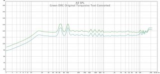
This is the graph of my current preferred target (Blue) vs DRC correction (Green) and your method with 1/24 FDW and Psychacoustic smoothing, both smoothed 1/6 after convolution. The main difference is down to applying the psychoacoustic smoothing when generating the filter so that could easily be changed.

I haven't listened to it as it is pure minimum phase and I am preferring phase correction below 1K so I would need to generate that in another filter to be able to compare them just on the frequency balance alone.
This is the graph of my current preferred target (Blue) vs DRC correction (Green) and your method with 1/24 FDW and Psychacoustic smoothing, both smoothed 1/6 after convolution. The main difference is down to applying the psychoacoustic smoothing when generating the filter so that could easily be changed.
Attachments

Nice work, fluid! Thanks for trying this out. It can seem a bit awkward at first, but it's not too bad once you get the hang of it. Nice to see you got similar results. I tried this method after a bit of difficulty really nailing down the low end response on my quasi-anechoic correction, but then I then I thought it might be fun for room correction too. I was surprised by how well it worked for me. I found the room response a bit too bright as shown, and added a 1 dB/oct tilt starting at 1kHz. Another thing I wanted to mention is that you can cut the work in half by doing an initial L+R avg. I can't say for sure since there are a few variables at play for me right now, but I think this might have subjective advantages as well.
mkane77g,
Yes, I would certainly recommend for anyone to get a feel for using these programs the correct way before delving into this silliness 🙂
mkane77g,
Yes, I would certainly recommend for anyone to get a feel for using these programs the correct way before delving into this silliness 🙂
Last edited:
I know you have mentioned using averaged measurements before but I can recommend using the vector average function in the newer release of REW it really does a good job of removing the position dependent room influence and leave the general trend in there. The more you average the more the room goes down, easily seen in an ETC. Seems a good way to me to get something approaching a quasi anechoic response but from the area you will be listening in.I tried this method after a bit of difficulty really nailing down the low end response on my quasi-anechoic correction,
My Left and right are quite different so I'm not sure if averaging them first would make things better but I haven't tried it to know. Getting them closely matched to help with stereo always seemed a good idea.Another thing I wanted to mention is that you can cut the work in half by doing an initial L+R avg. I can't say for sure since there are a few variables at play for me right now, but I think this might have subjective advantages as well.
Your method got me thinking that this could be a way of transforming a text file into an impulse as REW won't do that.
I tried converting one of my convolver filters to text and running it back through to see if I could get MP impulse out of it but I get this strange lift in the very top end which is not consistent with the text values.
I tried bypassing the Mic compensation or setting it flat but it doesn't seem to be that. Using less or more resolution in the text file doesn't change anything. The only think different in the DRC messages is that it has run out of room in the Hilbert transform stage, do you think that could be causing it and do you have any idea what I could try to avoid that lift?
Attachments
I thought I was using the most recent REW release, but I don't see an option for vector averaging (maybe I'm just missing it). Anyway, I used a very close mic placement for the nearfield portion of the NS3 measurement so the room really didn't come into play. I just couldn't get a perfect looking low freq response using the usual methods (maybe not even an audible difference in the end, but I was trying to avoid compounding errors).
Good point about left/right response matching and how that might play into the 2 channel average. My setup is symmetrical so it doesn't make a big difference either way. I'd be interested to know how it works for you.
Are you converting a non minimum phase impulse response to text format and back again? I haven't tried this but I think you would need to use PSFilterType = L (if you're not already). Also, just for best accuracy, try PSInterpolationType = H.
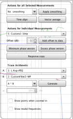
I am using Beta 6 but I think it was in Beta 5 as well, look in the All SPL controls here, (time align doesn't work well for me) the measurements selected at the bottom of the page (not shown) are the ones that will be averagedI thought I was using the most recent REW release, but I don't see an option for vector averaging (maybe I'm just missing it).
Mine is pretty symmetrical too but there are differences due to window placement etc.My setup is symmetrical so it doesn't make a big difference either way. I'd be interested to know how it works for you.
You can see in this shot that the two filters are quite different in some places but the average of the two channels tracks the target pretty well.
I tested a correction today based on just two positions where the ears would be in the sweet spot with no averaging and the result was not as good, it sounded quite "processed". Getting more of the room out of the base measurement worked better for me but I have quite a reverberant room with no treatment.
If you haven't tried it already I can really recommend wesayso's Mid Side EQ process. It really does make a difference on everything I have listened to. It needs to be linear phase EQ to work. I am using Fab Filter if you have that plugin I could send you a preset.
The filter did have excess phase but I wasn't trying to preserve it. I tested with PSFilter type as linear and it preserved the excess phase but still had the tilt. Interpolation from R to H made no difference. I tried band limiting the Dirac Pulse which worked to stop the Hilbert transform from overflowing but didn't change the output. It was worth a try though and could probably be fixed with a post EQ shelf if I really need to use that method.Are you converting a non minimum phase impulse response to text format and back again? I haven't tried this but I think you would need to use PSFilterType = L (if you're not already). Also, just for best accuracy, try PSInterpolationType = H.
Attachments

Thanks for the info; I'll check out that REW update.
If you want to try correcting based on a single measurement, I'd recommend a filter that is min phase and not more than 4 cycles resolution. The (DRC) psycho configuration I posted takes things a little further by relaxing the dip correction, and offers a lot of possibilities in terms of initial windowing/filter resolution. You can always add phase correction later just to compensate for the low freq rolloff of the system.
If you don't mind, try running DRC again with PSPointsFile = flat. The problem must be with either the impulse file or the text file...
Last edited:
Same thing happens, not sure why,

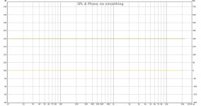
This is the impulse used as input, generated from Rephase

This template I am using now is heavily based on wesayso's settings, it has phase correction below 1K but only targeting a minimum phase response at the listening position. I would have to work out the number of cycles the filter is but it is longer on the top and bottom to help correct the array, I doubt it would work as well on a more conventional speaker. I have tried the same filter as pure minimum phase, the bass becomes a bit wild and boomy. On some tracks that can be great as a party effect but for me the phase correction is more accurate.
For now I prefer the corrections based on averaged measurements. If I had a treated room it might be different.
This is the impulse used as input, generated from Rephase
This template I am using now is heavily based on wesayso's settings, it has phase correction below 1K but only targeting a minimum phase response at the listening position. I would have to work out the number of cycles the filter is but it is longer on the top and bottom to help correct the array, I doubt it would work as well on a more conventional speaker. I have tried the same filter as pure minimum phase, the bass becomes a bit wild and boomy. On some tracks that can be great as a party effect but for me the phase correction is more accurate.
For now I prefer the corrections based on averaged measurements. If I had a treated room it might be different.
Attachments
Ok, so we know it's not the text file. Impulse looks good in that shot but just verify that the FR is perfectly flat. Assuming it is, it must be the config file...very strange. In the mean time, use the custom config file to convert the text file to an IR since you're only using the target response stage anyway. If you want to send me the config file, I'll take a look when I can.
Regarding phase correction in the lower octaves, my experience doesn't match your description of the difference between the filter types; I'd want to look at those settings. I'm not sure what you mean by the filter doing phase correction but targeting a min phase response at the listening position...
Regarding phase correction in the lower octaves, my experience doesn't match your description of the difference between the filter types; I'd want to look at those settings. I'm not sure what you mean by the filter doing phase correction but targeting a min phase response at the listening position...
FR looks straight to me 🙂

I'll test with one of your scripts that I haven't modified to see if that works properly
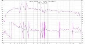
The phase correction is aiming to get as close to generated minimum phase as possible. This is what it looks like through an 8 cycle FDW. It's always difficult to compare the sounds of types of filters as there can be so many differences in other areas. I used REW to export a MP version of my correction IR with excess phase to compare and the template is quite different to yours so that could explain some of it.

I'll test with one of your scripts that I haven't modified to see if that works properly
The phase correction is aiming to get as close to generated minimum phase as possible. This is what it looks like through an 8 cycle FDW. It's always difficult to compare the sounds of types of filters as there can be so many differences in other areas. I used REW to export a MP version of my correction IR with excess phase to compare and the template is quite different to yours so that could explain some of it.
Attachments

I tried a few different things to try and get a flat response by using a Dirac pulse and flat target with no joy at all. I used your custom minimum phase template, bypassing the mic compensation, using flat.txt. I still get the lift which made me think it must be the impulse. I tried to manually set the impulse centre to 8192 which is where Audacity said it was as this was different to the value DRC gave in automatic mode. That just produced garbage. I tried moving the impulse to 1S exactly, same issue, if I set it back to automatic mode DRC reports 88200 as the impulse centre.
Could you test if you can get a flat response from a Dirac pulse and flat target? Not getting this working is starting to annoy me now 😡
Could you test if you can get a flat response from a Dirac pulse and flat target? Not getting this working is starting to annoy me now 😡
Thanks for that Greg they work 🙂
As soon as I opened them to compare in Audacity I could see where I had gone wrong. My Dirac Pulse was a stereo file and when it was being converted to 32bit float both channels were combined. Doh.
As soon as I opened them to compare in Audacity I could see where I had gone wrong. My Dirac Pulse was a stereo file and when it was being converted to 32bit float both channels were combined. Doh.
My averaged measurement looks very similar to a single central measurement in terms of FR when some smoothing is applied but I have found that you can apply stronger correction to it. The difference between a single measurement and averaged is quite audible. Try a stronger filter on the average and see if you like it more, it would be an interesting comparison to see if you find the same thing I did in my room.
I have tried the same filter as pure minimum phase, the bass becomes a bit wild and boomy. On some tracks that can be great as a party effect but for me the phase correction is more accurate.
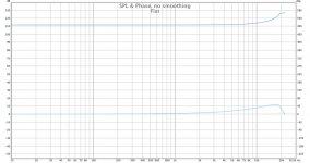
I think I may have found the reason why I noticed such a difference between the filters when I used REW to make a minimum phase version. This is the right channel with the filter applied, no wonder it sounded boomy and wild!
By using a minimum phase base measurement instead I get something much more reasonable, haven't tested it yet but just looking at the FR it should sound less wild.
Attachments

😱 I bet you can hear that difference!
Does this mean you now have a non excess phase corrected FIR filter to compare to the band pass min-phase targeted DRC correction?
Meaning no pré ringing etc? What does the IR look like?
Does this mean you now have a non excess phase corrected FIR filter to compare to the band pass min-phase targeted DRC correction?
Meaning no pré ringing etc? What does the IR look like?
Yes it does 🙂 So when I listen I will revise my thoughts as my previous impression was clearly due in part if not all to the FR issues.
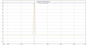
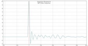
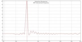
This is the minimum phase filters impulse response, no pre ringing.

This is the MP filter test convolution on Left Right Average. The pre ring there is due to the ADC and DAC filters and has not been corrected by DRC like it was with the excess phase correction.

This is the minimum phase filters impulse response, no pre ringing.
This is the MP filter test convolution on Left Right Average. The pre ring there is due to the ADC and DAC filters and has not been corrected by DRC like it was with the excess phase correction.
Attachments
- Home
- Loudspeakers
- Full Range
- A convolution based alternative to electrical loudspeaker correction networks