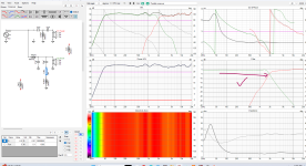
I did add the ressitsnc of the air core inductors. That's how I got above 3.9 ohm.Looks like a good start.
Depending on your answer to AllenB's question...may need to add y-offset.
If you use an air core inductor on the woofer that will add some DCR and i think raise the impedance a bit.
If you need to add a padding resistor to the tweeter, that raise the impedance a bit.
Overall, I doubt a low impedance will be a problem.
Search diyaudio and Tech Talk, maybe MAC, and see if you can find any posts on how low that tweeter can go. I did a quick search on my phone and didn't see anything, but I have those tweeters and looked into it before. I'm thinking 2.5khz but I put very little confidence in that recollection.
I'm just going to measure the tweeters and see how they do. I already have everything bought, and it was cheap, so I'll just wing this one. I'll porba my give it away to my brother when I'm done
Well that's good news. Once you start compensating the baffle, the added resistance might take care of your impedance difficulties.Just traced them.
Doesn't the baffle also have to get bigger to hold a bigger woofer?if the driver is so large that it beams before the baffle step occurs. That usually happens with 15"+ drivers.
Doesn't the baffle also have to get bigger to hold a bigger woofer?
While that's true it doesn't prevent the baffle step to apply. A bigger baffle pushes the BS down unless the driver starts to beam before the baffle step applies (often at 12" and up). No dispersion at that frequency, no baffle edge reflection. According to your speaker building history and experience I really expected you to know that. Especially since your XO thread is pinned up for newbies to follow. It's probably time to update it.
This is fallacy because the beaming frequency depends on the size of the driver, which determines the size of the baffle.
Why do you feel that questioning my knowledge of the subject somehow changes that?
Why do you feel that questioning my knowledge of the subject somehow changes that?
For the woofer, I'd play around with some notch filters (series LCR, in place of the 100uF you had at the start) to try and get rid of the peak around 5kHz. Possibly drop the 1.2mH inductor altogether, as the notch should combine with speaker response to produce a roll-off on its own.
For the tweeter, keep the capacitor and size it get roughly the right amount of overlap, and do listening tests with a small selection of different series resistors for padding, to get the right bass/treble tonal balance.
Don't get caught up in the race for frequency flatness, because it's not even a good measure of "good sound". It's just one indicator of many. You still need to manually plug components in and listen to every change.
I don't really understand this impendence dip that is causing my XO to go all funky. I'll pull the theile small parameters as I don't think the traced impendence is correct
How does your crossover look like?
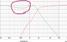
I don't really understand this impendence dip that is causing my XO to go all funky.
It does not appear to be impedance, at all.
It does not appear to be impedance, at all.
Yes, that's not the impedance but the frequency response.
I think he meant that the impedance is low in that range and causes the dip in the FR.
It is the filter (transfer function?) and labeled impedance in the VituixCAD pane, which is why he is saying "impedance".
Try increasing the coil and reducing the capacitors from woofer filter. Adding a small capacitor (eventually series with a small resistor) in parallel with woofer coil to create a notch at ~5Khz will attenuate the peak in woofer response.I don't really understand this impendence dip that is causing my XO to go all funky. I'll pull the theile small parameters as I don't think the traced impendence is correct
That's not an impedance dip. That graph is the transfer function. Essentially what your crossover components are doing to attenuate the response. and therefore shape the final acoustic response (top left) of the drivers which sum to the overall system response.I don't really understand this impendence dip that is causing my XO to go all funky. I'll pull the theile small parameters as I don't think the traced impendence is correct
The bottom right is your impedance by frequency. If you are using a solid state amplifier, then a "rule of thumb" I've seen from others is to keep the impedance phase to <= 45 degrees. A flat impedance does this, but having peaks in your impedance isn't a problem for many sold state amps, as long as the impedance phase isn't swinging wildly to extremes (e.g. >= 60 degrees)
I will pull the impendence off the actual driver soon. Will post up when I have it.Any chance you could post the impedance file?
I have some other things to get to this week.
Dave,
I noticed that I can throw a resistor to ground inline with the initial power wire and the sim will show it smoothing out my impendence. I have never actually done this on a build though. Do you know why this or have any experience with the effect of the sound on the system?
I noticed that I can throw a resistor to ground inline with the initial power wire and the sim will show it smoothing out my impendence. I have never actually done this on a build though. Do you know why this or have any experience with the effect of the sound on the system?
Doing that will swamp the impedance variations but it comes at the cost of extra power the amplifier needs to supply.
This is not necessary with a regular audio amplifier since the effect of impedance variations is negligible.
This is not necessary with a regular audio amplifier since the effect of impedance variations is negligible.
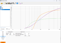
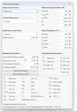
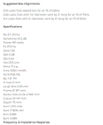
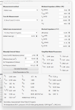
Has anyone EVER seen a driver's stated Thiele small parameters off this far? Green line is with stated specs. The rest of them are what I actually measured. I added 9 grams to the cone.
I am attaching the impendence measurement so you all can see for yourself.
This is so far off I feel like I did something wrong. But I know I didn't...
I am attaching the impendence measurement so you all can see for yourself.
This is so far off I feel like I did something wrong. But I know I didn't...
Attachments
-
 Screenshot 2024-09-05 135305.png21.5 KB · Views: 57
 -
 Screenshot 2024-09-05 135257.png25.2 KB · Views: 68
 -
 Screenshot 2024-09-05 135241.png19.7 KB · Views: 64
 -
 Screenshot 2024-09-05 133642.png27.1 KB · Views: 62
 -
Silver FLute 6.5 4 ohm.mdat904.1 KB · Views: 41
-
Silver Flute 6.5 9 grams.mdat904.1 KB · Views: 47
-
SilverFlute.zma17 KB · Views: 39
Last edited:
Did you break in the driver? If so how? You need to wait briefly depending on how long / hard you break it in to let the voice coil cool and reduce resistance due to heat.
Some driver manufacturers use a higher level drive voltage (power) for TSP measurement (even though they are small signal parameters!). For example, I can never get my SB Acoustics drivers to measure as per factory via DATSv3.
Also - I believe delta compliance (known sealed box volume) is more accurate than added mass for TSP measurement, but whether it can make up for that discrepancy, I'm not sure.
- Home
- Loudspeakers
- Multi-Way
- A boring 2 way build
