The low Rp helps greatly reduce the output impedance of an OTL, with little need for paralleling, which coincidentaly will generate as much, if not more heat, and add other complexities.
If you want simple, a good EL34 will do nicely in PP - transformers are actually pretty good devices, and they allow you to simplify the circuit in many other ways, reducing the variables... OTL has its price - and often that price whilst superficially may be worth paying (no transformer), the long term price may be too high (issues with slew rate from the driver stage, variation of tube characteristics, complexity and so on).
Dont forget the high componant count too - they will (if boutique parts are used) bump up the cost above and beyond the price of a great transformer, or two.
Have fun
Owen
Hey owen-
I think we have minor misunderstanding. I don't intend an OTL amp, rather I am looking at their topology/tube choice as a means of reducing the winding ratio of the OT. I'll probably be winding my own, and I can use any advantage I can find 😉 .
Of course if someone has an OTL recommendation with no more than 2 tubes in the output stage that can throw 10-20 watts into a half ohm load I'll bite 😀
Casey
Casey,
No misuderstanding here - they are great if you want the pure DIY route...
I would (personally) strongly consider a derivative of the splitload phase splitter on steroids...
As an output stage, it has a gain of 2. So it is actually a voltage-current converter, and a great tube would be the 6c33 - if you can find a sweet operating spot around 30W or so, it should make you weep with joy for the 8 - 12 W of pure PP Triode power you'll get out. You should also be able to easily step the impedance up from your .5 ohm to a more managable 500 or so - the 'sweet spot' for this tube.
To do this the primary must be rated 220V, the secondary rated as 6V - a 50VA transformer should do the trick, but I'd err on the side of caution and look for a 75, or 100VA - the wire gauge, and the core will be much bigger - lowering distortion.
The key to this stage design, is that the current in the primaries MUST oppose to null to negate the DC saturation. This is possible, as the phase of the signal on each leg is inverted - so when you reverse the current flow through on primary leg, the signal SUMS - hence the gain of 2.
To drive this, you will need a high current, high gain tube - the EL84 springs immediately to mind.
The PSU design would be straightforward, and no tube matching trickiness either.
The transformer I would use - a mains torroid. Mass produced, tightly wound, easily available, and in general, cheap. Transformer winding is a slow, painful work.
Just to put some :evil: thoughts out there 😉
Take care, and keep on having fun !
Owen
valveitude said:It is an issue, however there are means to control it. First, as you point out, a proper high pass. I found that a dual slope with a very steep second pole an octave or so below the x-over point does wonders. The majority of the ribbon movement is caused by infra-sonic garbage. I also found that when playing loud and the ribbon wanted to pull out of the gap I could barely touch it to push it back in. This led me to the conclusion that the force on the ribbon was very small indeed. I found that felt "bump stops" cured the problem with no noticible sonic side effects.
Casey [/B]
You mean something like that:


thanks!
fivestring-
Yep..though you may have gone a little overkill though 😉 . I found just one about an 1/8" wide in the middle of my 60" ribbon enough to tame it. I'm sure your approach works just fine.
Your most welcome.
Casey
You mean something like that:
Yep..though you may have gone a little overkill though 😉 . I found just one about an 1/8" wide in the middle of my 60" ribbon enough to tame it. I'm sure your approach works just fine.
thanks!
Your most welcome.
Casey
Sheesh..you know it's been too long since your last post when you have to do search to find the thread 🙄
Before I get into the much delayed progress, an example of what happens when you unplug the patch going to the UcD400 feeding the ribbon by mistake (well second mistake actually..I should have turned off the system before reaching for the cable)...
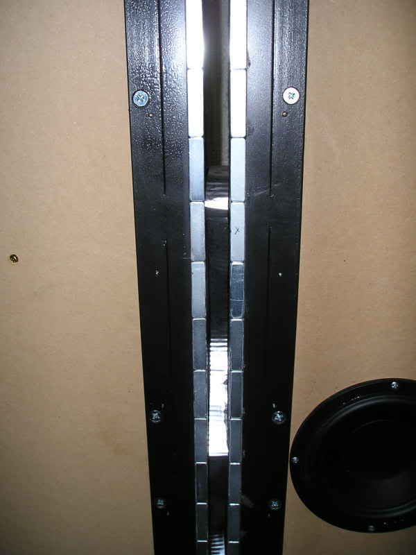
Oopsies 😀 . Can you imagine how a fella would have felt doing this to a comparable commercial ribbon? As it is, an hour later it was online again with a fresh ribbon..VIVA la DIY!!!
The delay in any work was due to a couple of reasons, life kept getting in the way stealing my time, and I really needed to gird up my loins for the task ahead. As I put my thoughts on my new baffle design in CAD I came to the inescapable conclusion that I was FAR from done in spite of the tremendous effort expended thus far. I had to wait until I tired of "listening around" the aberrations of my "scabbed" together baffle.There are 4 basic problems that I can no longer tolerate. 1)An unholy alliance between the baffle step, natural resonance of the poorly supported baffle, and a room node. These three things conspire to give a mid bass bump that makes a lot of music un-listenable. 2) The bass driver vibrating the speaker as a whole smears the leading edge of percussion instruments smearing the "attack" considerably 3) The single Extremis per side bottoms way to early...this has gotten worse as the drivers have broken in. 4) The edge diffraction off the magnets imparts a "hardness" in the upper registers of some music.
I have come to the same conclusion that many of the top cabin ribbon mfg.'s have...the portion of the baffle supporting the bass divers MUST be completely Isolated from the ribbon itself. It took me a bit to figure out how to do this with the baffle shape I had in mind. Once I did I realized just how much work is involved. I'm not going to explain it all, but it will reveal itself as I post the progress.
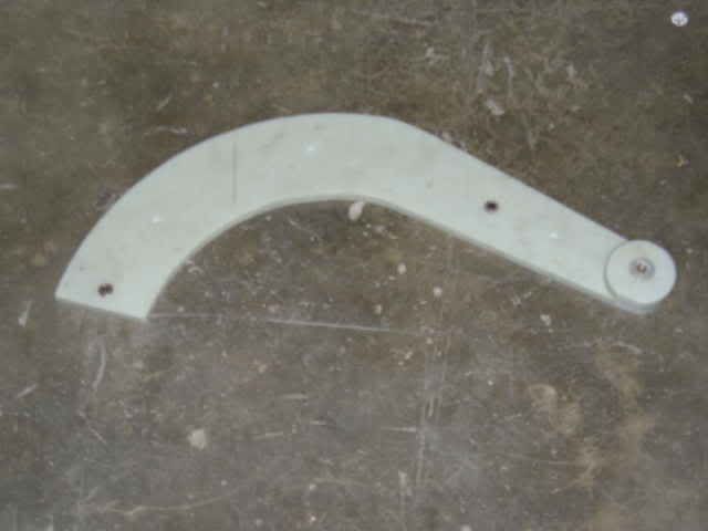
The first part of the work is unfortunately not documented..kept forgetting to charge my camera batteries...but it involved cutting out, and routing, 64 pieces of 1" MDF using this jig on a makeshift routing table...
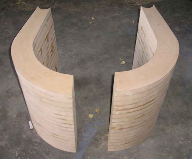
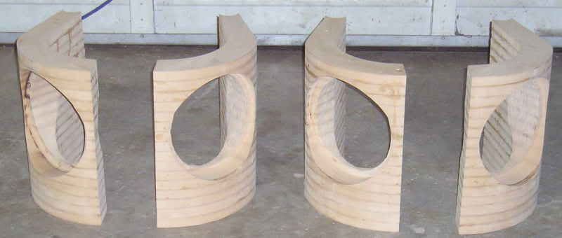
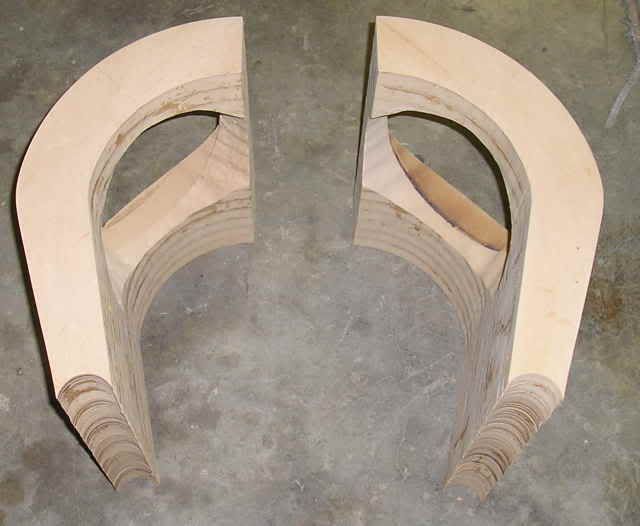
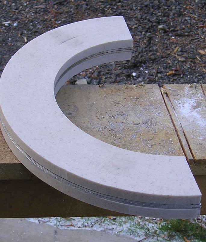
What seemed like an eternity later, I had the basic pieces of the bottom of the baffle laminated together...
I then fabricated the tooling needed to cut out the spaces for my drivers in the curved section of the material, layed out my angles and mounted the piece up...
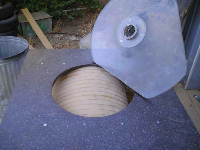
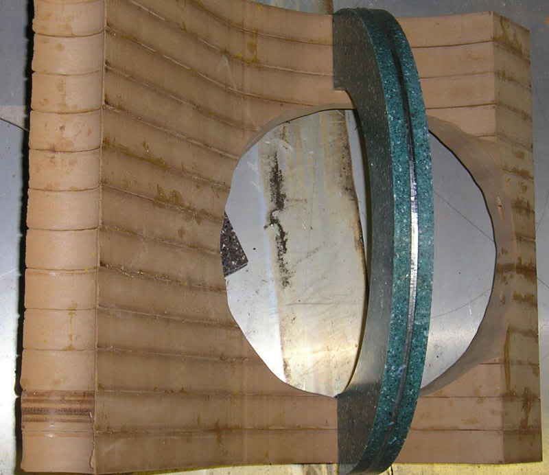
The ring around the router bit rubs on the circle cutout giving me my circle guide. Let the games begin...
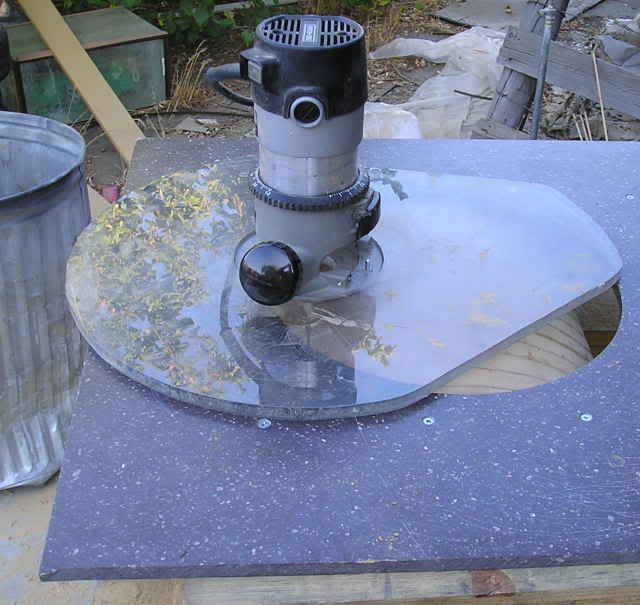
About 3 hours later, and a final pass with a bigger ring to give me a guide for the hole
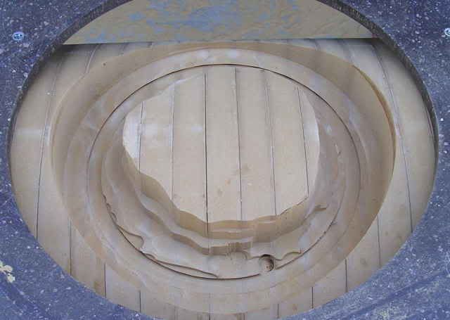
...I'm ready for the chain drilling...
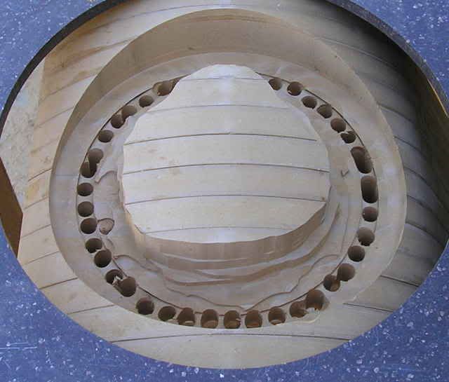
...and the sawing...
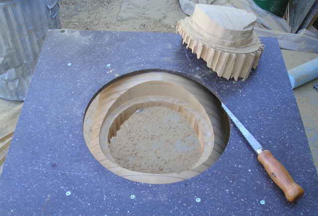
...and the grinding/sanding...

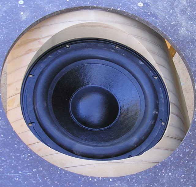
An hour or so later a Exodus DPL-10 test drives it's future home...
Repeat as needed...
All told I estimate about 80 hours of labor intensive work to get to this point. If I never turn my router on again, that would be OK 😉. I literally filled a garbage can to the halfway mark with MDF dust.
I'll continue to post the progress,
Casey
Before I get into the much delayed progress, an example of what happens when you unplug the patch going to the UcD400 feeding the ribbon by mistake (well second mistake actually..I should have turned off the system before reaching for the cable)...
Oopsies 😀 . Can you imagine how a fella would have felt doing this to a comparable commercial ribbon? As it is, an hour later it was online again with a fresh ribbon..VIVA la DIY!!!
The delay in any work was due to a couple of reasons, life kept getting in the way stealing my time, and I really needed to gird up my loins for the task ahead. As I put my thoughts on my new baffle design in CAD I came to the inescapable conclusion that I was FAR from done in spite of the tremendous effort expended thus far. I had to wait until I tired of "listening around" the aberrations of my "scabbed" together baffle.There are 4 basic problems that I can no longer tolerate. 1)An unholy alliance between the baffle step, natural resonance of the poorly supported baffle, and a room node. These three things conspire to give a mid bass bump that makes a lot of music un-listenable. 2) The bass driver vibrating the speaker as a whole smears the leading edge of percussion instruments smearing the "attack" considerably 3) The single Extremis per side bottoms way to early...this has gotten worse as the drivers have broken in. 4) The edge diffraction off the magnets imparts a "hardness" in the upper registers of some music.
I have come to the same conclusion that many of the top cabin ribbon mfg.'s have...the portion of the baffle supporting the bass divers MUST be completely Isolated from the ribbon itself. It took me a bit to figure out how to do this with the baffle shape I had in mind. Once I did I realized just how much work is involved. I'm not going to explain it all, but it will reveal itself as I post the progress.
The first part of the work is unfortunately not documented..kept forgetting to charge my camera batteries...but it involved cutting out, and routing, 64 pieces of 1" MDF using this jig on a makeshift routing table...
What seemed like an eternity later, I had the basic pieces of the bottom of the baffle laminated together...
I then fabricated the tooling needed to cut out the spaces for my drivers in the curved section of the material, layed out my angles and mounted the piece up...
The ring around the router bit rubs on the circle cutout giving me my circle guide. Let the games begin...
About 3 hours later, and a final pass with a bigger ring to give me a guide for the hole
...I'm ready for the chain drilling...
...and the sawing...
...and the grinding/sanding...
An hour or so later a Exodus DPL-10 test drives it's future home...
Repeat as needed...
All told I estimate about 80 hours of labor intensive work to get to this point. If I never turn my router on again, that would be OK 😉. I literally filled a garbage can to the halfway mark with MDF dust.
I'll continue to post the progress,
Casey
A question to those who use long line source planars: don`t linesources cause tall soundstage, like singer`s mouth from the floor to ceiling?
Charcoal said:A question to those who use long line source planars: don`t linesources cause tall soundstage, like singer`s mouth from the floor to ceiling?
That`s the problem of recording method and not the tall line source planars. Close miking produces exaggerated images and unnatural timbre. At concerts nobody listens to instruments and voices from a few inches, so why record them that way? When recordings are made correctly, planars reproduce them faithfully, much more realistically than point sources.
I believe close making was "invented" because of the inability of small point source loudspeakers to adequately reproduce life sized images.
Casey, Nice to hear from you again. I sure hope you were wearing a respirator and had a fan going. Nice shape. Router bit turned kinda red did it not. The mdf glue is murder on tools.
How did you come by the math for that particular piece of artwork?
If you can find a couple of Mc3500 tooob amps I believe they will drive your half ohm faithfully. Suppose to handle dead shorts. Just a little on the pricey side for my budget.
What is the spec on the thickness of ribbon you are using in these units after all of the experiments?
Tad
Hi Charcoal
What five string said 😉 . I would just add that all configurations (point, line, omni) have tradeoffs involved...for me, dipole line sources have the best compromises. The review critters tend to agree as they consistently come out "best of show"
tryonziess-
All this work was done outside in the breeze.
In the next to last pic you'll notice the piece on the left got a little crispy. I had to cut in 2 1/2" at the deepest point and the only thing I had on hand to reach was a metal cutting endmill...smoke city. After that I went shopping and found a proper router bit that would work. Going slow with shallow cuts prevented any more burning.
I stink up the place doing math 😀. I relied on dipole spreadsheets to determine my target effective width, then played around with cad to get the profile I could live with. Once there, I printed out a template to cut my pattern with.
Approximately 6 micron harvested out of a capacitor..I would like to experiment with some thinner stuff if I could find it.
Casey
A question to those who use long line source planars: don`t linesources cause tall soundstage, like singer`s mouth from the floor to ceiling?
What five string said 😉 . I would just add that all configurations (point, line, omni) have tradeoffs involved...for me, dipole line sources have the best compromises. The review critters tend to agree as they consistently come out "best of show"
tryonziess-
I sure hope you were wearing a respirator and had a fan going.
All this work was done outside in the breeze.
Router bit turned kinda red did it not
In the next to last pic you'll notice the piece on the left got a little crispy. I had to cut in 2 1/2" at the deepest point and the only thing I had on hand to reach was a metal cutting endmill...smoke city. After that I went shopping and found a proper router bit that would work. Going slow with shallow cuts prevented any more burning.
How did you come by the math for that particular piece of artwork?
I stink up the place doing math 😀. I relied on dipole spreadsheets to determine my target effective width, then played around with cad to get the profile I could live with. Once there, I printed out a template to cut my pattern with.
What is the spec on the thickness of ribbon you are using in these units after all of the experiments?
Approximately 6 micron harvested out of a capacitor..I would like to experiment with some thinner stuff if I could find it.
Casey
Casey, Does this long of a ribbon handle the top end real clear. What would you suggest are the effective low and high ranges for your ribbon.
Been hoarding stuff for my pair. The magnets are expensive retail. Just gotta have em'
Would adding a plate on the corners help any with your PROJECTED over saturation in that area. Thanks Tad
PS. How are you able to use corian as a pattern for stuff. That material is like gold. But it machines real nice.
Does this long of a ribbon handle the top end real clear. What would you suggest are the effective low and high ranges for your ribbon.
I haven't got my measurement set up done so no actual FR test, but, I haven't seen a ribbon yet that didn't do 20khz+. As for the low end, thats the challenge. My set up crosses over at 200hz.
Would adding a plate on the corners help any with your PROJECTED over saturation in that area
I wouldn't bother.
PS. How are you able to use corian as a pattern for stuff. That material is like gold. But it machines real nice.
My brother works at a large cabinet shop and has arranged to get "end cuts" from the Corion shop when available..S-w-e-e-t 😀
Casey
Due to poor planning (didn't get my epoxy ahead of time), and an equipment failure (band snapped in my saw) I didn't get anywhere near where I wanted to this weekend..oh well.
First up some more quality time with my router. I sandwiched up some aluminum sheeting with some Corion, and cut out four sets of circles...
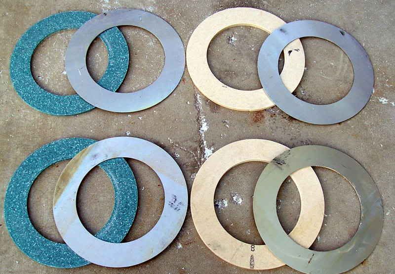
These I bisected and glued/screwed together (this pair hasn't been glued yet, but you get the idea)..
These Corion/aluminum laminates will fit on the back of the baffle perpendicular to the drivers thusly...
When done, the two braces will meet at a sand filled pipe spiked to the floor..yeah baby!!
I was really hoping to have everything ready for assembly next weekend, I guess it wasn't meant to be.
Casey
First up some more quality time with my router. I sandwiched up some aluminum sheeting with some Corion, and cut out four sets of circles...
These I bisected and glued/screwed together (this pair hasn't been glued yet, but you get the idea)..
These Corion/aluminum laminates will fit on the back of the baffle perpendicular to the drivers thusly...
When done, the two braces will meet at a sand filled pipe spiked to the floor..yeah baby!!
I was really hoping to have everything ready for assembly next weekend, I guess it wasn't meant to be.
Casey

Has your wife given you the o.k. to drill and tap a nice big hole in her living room floor.
What brand and spec are the 4 bass units you are using. Will they extend to the full 200hz left from the ribbon?
Here you go again, Casey. Tad
What brand and spec are the 4 bass units you are using. Will they extend to the full 200hz left from the ribbon?
Here you go again, Casey. Tad
Has your wife given you the o.k. to drill and tap a nice big hole in her living room floor.
No wife to ask permission from, regardless, it will simply have a speaker stand spike on the end that mates the floor..no drilling involved.
What brand and spec are the 4 bass units you are using. Will they extend to the full 200hz left from the ribbon?
The Exodus DPL-10 from DiyCable. According to them it should go past 1 khz no problem.
Here you go again, Casey
It's a sickness

Casey
I started on the custom brackets to fasten the braces behind the drivers. The only suitable material I had on hand was a piece of hot rolled steel and some powder coated pipe. Since these need to be welded, I spent a big chunk of my time grinding scale, and wire wheeling off powder coating..good times 🙄 . Here is the progress made. Pieces cut out, and one set almost done..
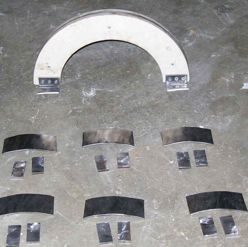
As usual, I didn't get near as far as hoped..I'm learning to take it in stride 😉 .
Casey
As usual, I didn't get near as far as hoped..I'm learning to take it in stride 😉 .
Casey
Casey, You seem to have this project pretty much in hand. How is the current drive tooob amp design going. I think that is what you originally proposed. No transformer on the ribbbon input and lots of tooobs for power.
Would there be in benefit of capturing some of the ribbons energy from the rear and focusing it forward. There is just as much sound radiating rearward as forward and all into the sheetrock wall.
The current bass speaker project is open with no baffle correct? Without a box or cone will this give you the needed sub frequency or are you going to handle that with a third item.
More Corian $$$, some folks are just lucky.😎 Tad
How is the current drive tooob amp design going. I think that is what you originally proposed. No transformer on the ribbbon input and lots of tooobs for power.
It's still on the drawing board. It will be a typical output topology with transformer wound for 1/2 ohm load
Would there be in benefit of capturing some of the ribbons energy from the rear and focusing it forward. There is just as much sound radiating rearward as forward and all into the sheetrock wall.
It's a dipole..the backwave is used to cancel the side lobes giving a quasi figure 8 dispersion pattern. My room is to small to get them as far from the wall as I would like, so I hung some drapes behind to help..and it did.
The current bass speaker project is open with no baffle correct? Without a box or cone will this give you the needed sub frequency or are you going to handle that with a third item.
The bass modules are dipole as well. They have a baffle..that big pile of mdf I've been cutting up. It will all make sense soon.
Casey
- Status
- Not open for further replies.
- Home
- Loudspeakers
- Planars & Exotics
- A 60" Ribbon w/TL Loaded Extremis Hybrid