remember the musical "Hello Dolly"?
well forget the music part and get yourself a dolly 🙂
well forget the music part and get yourself a dolly 🙂

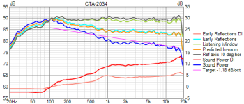
The Fs in test (open) baffle is 31Hz, now it doubled in your box... But I guess it can take enough power to eq in-room response nice
Indoor measurement with such long gating (below 200Hz) is not very reliable (room modes interfering), but normalized directivities look realistic to me 🙂
ps. The speaker looks fantastic!
Indoor measurement with such long gating (below 200Hz) is not very reliable (room modes interfering), but normalized directivities look realistic to me 🙂
ps. The speaker looks fantastic!
Last edited:
Wonderful Vineeth!
Now all we need is one the size of a modern TV (ie. <6" deep)
Now all we need is one the size of a modern TV (ie. <6" deep)
Those who might critisize the size of the speaker, please remember that Vineeth's apartment is echoey and this is a mission to fight against that. To achieve cardioid bass and high directivity you must use large drivers and/or horns. No free meals... 😎
Thank you @Juhazi 🙂
In fact I was trying out exactly what you said.. to see if I can get better sound than my current systems in this echo chamber..
I am aware that Kimmosto has gone to great lengths making a horn + dual 18inch driver-based cardioid system etc, and eventually concluded that even though such a system sounds good enough, often a low directivity system with proper room acoustics sounds better(?)..
But this is just my attempt along similar lines (though not comparable to his system) + just having fun building speakers..
Someday, I may have a dedicated listening room, etc.. but until then, this fight continues.. 🙂
@tktran303: I too like slim (not deep) speakers if they don't compromise on the sound.. 🙂
We might get to such speakers soon, I guess, given the kind of drivers available out there..
This current system of mine is about 12 inches deep. I like the aesthetics of this one better than all the other speakers currently at home.. 😀
My wife likes it too (Lucky me.. 😉 )
A friend of mine has been building a wide radiating speaker system with Purifi 10 inch in a sealed box + Bliesma beryllium mid and beryllium tweeter on a waveguide. That one is just 8inches or so deep. Its baffle looks like this..
You might be interested in that one.. 🙂
Another version of the crossover..
Crossover V2


This time the idea was to smoothen the DI knee in the 100 to 300 Hz region..
Earlier crossover (v1)

New crossover (v2)

Crossover V2
This time the idea was to smoothen the DI knee in the 100 to 300 Hz region..
Earlier crossover (v1)
New crossover (v2)
I tested this crossover first on one speaker (as an experiment)


Measurement from MLP

Measurement from MLP
I think this thread has become very long with not much connection to the original premise.. Well, still I am making 3 way speakers mostly (been occasionally making 2ways and 2.5 ways? but there has been quite a few different iterations like below
1) The original small waveguide tweeter + SB15CAC mid + Satori WO24Ps
2) The smaller cardioid 3way
3) The current big driver 3way, etc..
Maybe, I should create and index and a summary in the first post of the thread...
1) The original small waveguide tweeter + SB15CAC mid + Satori WO24Ps
2) The smaller cardioid 3way
3) The current big driver 3way, etc..
Maybe, I should create and index and a summary in the first post of the thread...
Creating an index is easy to do with the new features in the upgraded website software. Being able to forever edit the first post in a thread is very useful for this...
I have not been able to do much audio related things recently because of work pressure.. But I have been trying to listen to the system whenever possible and make improvements in crossover.. 🙂 Probably i will get some time to spend some quality time in the second half of December.
This is how the system is now


Crossover looks like below (can be simplified further)
Please ignore the gain on the subwoofer branch


There is a significant excess group delay increase around 100Hz with the above crossover (4.4ms)
The LR4 phase linearization around 100Hz can get rid of it and make it like below. But my minidsp probably won't handle that kind of FIR filter


This is how the system is now
Crossover looks like below (can be simplified further)
Please ignore the gain on the subwoofer branch
There is a significant excess group delay increase around 100Hz with the above crossover (4.4ms)
The LR4 phase linearization around 100Hz can get rid of it and make it like below. But my minidsp probably won't handle that kind of FIR filter
I have lot more subjective impressions to tell about.. I will post it during next break.. 🙂
Very cool, really excellent project.
I have also found that the typical subwoofer crossover below 100 Hz can introduce a lot of group delay. Some people are sensitive to this, while most are not affected.
I am not sure I fully understand your configuration, so take this observation as tentative: I noticed that the NeroSW800 has a delay of 375 us. But that driver is further away from the listener than the other two drivers, and normally we would add delay to the closest driver. In your VituixCad simulation, you have the NeroSW800 driver with a Z dimension of 300 mm, so it is modelled as being 300 mm further away from the listener, and having an additional 375 us of delay. Is this what you actually intended?
j.
@grindstone: You are very correct there.. 😀 😀
@hifijim: Thank you.. 🙂
Actually I adjusted the delay to get the pattern control as per taste/requirement.
The basic idea is to manipulate the phase of the subwoofer driver such that it creates constructive/destructive interference in the frequency range that we need.
Ideally, we want constructive interference between below 80-100Hz such that the polar pattern is omni since there is not probably much to be gained with pattern control below that. Above 100Hz, we want to make the mid driver and sub driver interfere destructively such that it creates the cardioidish pattern.
Here is an example with different delays on the sub-driver branch. compare the trends in phase, SP DI knee around 100Hz and nulls in the polar pattern around 100 Hz (occurring due to the manipulated destructive interference)
1) delay = 0


2) delay = 375us


Comparing with delay =0, now the SP DI knee has become ever so smoother, the nulls in the 100 to 200Hz region become shallower due to the drivers becoming more in phase around 100Hz
2) delay = 750us


Comparing with delay =0, and delay =375us, now the SP DI knee has become visibly smoother, the nulls in the 100 to 200Hz region become even more shallow due to drivers being in phase. But now there is nice transition in SP DI curve compared to the other cases..
So, in summary, the delay adjustment helps control the pattern as per the requirement (at least to some extent)..
This whole trick, I picked up from @fluid's posts from long back.. 🙂
@hifijim: Thank you.. 🙂
Actually I adjusted the delay to get the pattern control as per taste/requirement.
The basic idea is to manipulate the phase of the subwoofer driver such that it creates constructive/destructive interference in the frequency range that we need.
Ideally, we want constructive interference between below 80-100Hz such that the polar pattern is omni since there is not probably much to be gained with pattern control below that. Above 100Hz, we want to make the mid driver and sub driver interfere destructively such that it creates the cardioidish pattern.
Here is an example with different delays on the sub-driver branch. compare the trends in phase, SP DI knee around 100Hz and nulls in the polar pattern around 100 Hz (occurring due to the manipulated destructive interference)
1) delay = 0
2) delay = 375us
Comparing with delay =0, now the SP DI knee has become ever so smoother, the nulls in the 100 to 200Hz region become shallower due to the drivers becoming more in phase around 100Hz
2) delay = 750us
Comparing with delay =0, and delay =375us, now the SP DI knee has become visibly smoother, the nulls in the 100 to 200Hz region become even more shallow due to drivers being in phase. But now there is nice transition in SP DI curve compared to the other cases..
So, in summary, the delay adjustment helps control the pattern as per the requirement (at least to some extent)..
This whole trick, I picked up from @fluid's posts from long back.. 🙂
Attachments
I am confused, should the delay of the woofer not be negative, iow, in the direction of the listeners?
Last edited:
Now I am confused as well.. 🙂
The negative delay in the simulator just changes the location and depth of nulls and impacts all the response curves accordingly..
WIth delay = -375us


But based on my understanding so far, increasing the delay probably increases the "acoustic center" (for the lack of a better term) distances (distance between the source formed by the mid driver and source formed by the sub driver probably weakening the cancellation effect.. This is what we see in graphs in previous post.
Applying negative delay brings the acoustic centres close and makes the cancellation effects stronger, deepening the nulls above 100 Hz (due to the relative phase matching at different angles in that region) as seen in pic above..
The negative delay in the simulator just changes the location and depth of nulls and impacts all the response curves accordingly..
WIth delay = -375us
But based on my understanding so far, increasing the delay probably increases the "acoustic center" (for the lack of a better term) distances (distance between the source formed by the mid driver and source formed by the sub driver probably weakening the cancellation effect.. This is what we see in graphs in previous post.
Applying negative delay brings the acoustic centres close and makes the cancellation effects stronger, deepening the nulls above 100 Hz (due to the relative phase matching at different angles in that region) as seen in pic above..
- Home
- Loudspeakers
- Multi-Way
- A 3 way design study