I would describe it as a resistive slot or leaky enclosure to increase low and mid frequency directivity control.
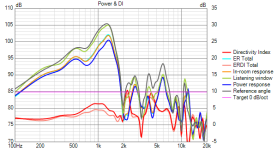
In the graph the lowest DI is 6dB which is closest to Hypercardioid (as a descriptor) and rises from there.
You might call a spade a shovel or vice versa and most people will understand your meaning. Not everyone will realise that there actually is a difference and even less will care either way.
In the graph the lowest DI is 6dB which is closest to Hypercardioid (as a descriptor) and rises from there.
You might call a spade a shovel or vice versa and most people will understand your meaning. Not everyone will realise that there actually is a difference and even less will care either way.
Prototype measurement time 😀
Here is the ugly cabinet made for the MEH using XPS foam and hot glue (I know that it will not win any prizes for looks or functionality.. That thing causes its own sweet resonances 😛 😀)

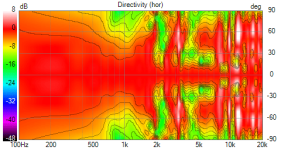
Measurements were made only out to 90 degrees. Measuremets were gated at 4ms..
Hence the masking of high Q resonances in the passband are also probably there..
Anyway, here is how the highs on Rosso 65CDN-T look like (Normalized 20 degrees off axis)


Now the mids (2xTC9FD in closed box of 10+ litres volume)


And here is a rough crossover that stitches together the two sets of drivers (Off course it can be done infinitely better 😀 )


Here is the ugly cabinet made for the MEH using XPS foam and hot glue (I know that it will not win any prizes for looks or functionality.. That thing causes its own sweet resonances 😛 😀)
Measurements were made only out to 90 degrees. Measuremets were gated at 4ms..
Hence the masking of high Q resonances in the passband are also probably there..
Anyway, here is how the highs on Rosso 65CDN-T look like (Normalized 20 degrees off axis)
Now the mids (2xTC9FD in closed box of 10+ litres volume)
And here is a rough crossover that stitches together the two sets of drivers (Off course it can be done infinitely better 😀 )
Attachments
Last edited:

How about moving the crossover point lower than 1kHz? Would it break directivity?
It's surprisingly good. There's no point moving the crossover frequency lower if everything works this well.
But for such a moderately high crossover frequency, you could use a small 1" driver and save some space around the throat, and improving the top octave, IMO.
But for such a moderately high crossover frequency, you could use a small 1" driver and save some space around the throat, and improving the top octave, IMO.
@meiro.. I will be using a 1inch driver (B&C DE360) and 4 x B&C 4NDF34 drivers per side in the final build/horn... Hence this choice of 1.5ish kHz crossover frequency.. 🙂
@mabat: Thanks.. 🙂
I am already encouraged by the relatively smooth directivity transition near the crossover area (except the mismatches caused by crossover).. The horn seems to be holding the directivity even through mids are coming from a different source than the exact throat.. 😀
At the moment, the centre of throat to mid port centre distance is 6cm, which which is less than 1/4th wavelength at crossover frequency of 1.32kHz (wavelength approx 25cm)..
Shiny new things from TLHP are here.. 😀
These things give me such joy.. 😀 😛


These things give me such joy.. 😀 😛
I have tymphany DFM 2535, 2544, and BMS 4550 also competing for a position on the horn.. 😀 Will try them out if the B&C DE 360 is not ready for it.. Somehow I was too much attracted by the DE 360's break up free response upto 20kHz.. and I will never exceed 100dB SPL per side at home.. So...
Just out of curiosity, I tried to do one more quick iteration of the crossover but results are mostly the same..


It seems like the acoustic low pass filtering of the mids sort of determines the crossover slopes between the mids and highs to a large extent.
Maybe there is some optimization possible there, also focussing on the out-of-band (for the mids) garbage supression for the mids.. That may help with a little bit smoother transition in directivity I guess, in the crossover region..
I also probably need to have some standoff to reduce the volume under the mid cones as seen in this nice thread: https://www.diyaudio.com/community/threads/two-way-synergy-horn.367812/post-6567410
As of now, DSP and especially FIR filtering with steep slopes seems the better option..
I had thought of trying out Coherent midrange integrator (http://pro-pa.com/index.php?id=2059) sort of things applied to the mid's ports initially, but given the iterations needed to get something that works properly and give visible/hearable benefits, I am a little hesitant to move forward with it..
Given that the waveguide largely determines the overall directivity, I will work to see if I can do anything more in that area and start modifying it in fusion 360 for the new mids & CD and get to 3D printing it fast.. 😀
That can give a false impression of the DI. Instead of 8 to 10 in the 4pi simulation you have 5 to 7 from the quasi 2pi measurements.Measurements were made only out to 90 degrees.
@fluid: I completely agree.. I have been noticing this with measurements of the EXAR 400 horn and the mk3b2 build as well.. 🙂 Another 0.5 to 1dB DI delta might occur in this case due to lack of vertical polars I think..
In fact, I probably want the DI more in the 8dB region above 1kHz and slowly coming down in value to cross over properly with the 15inch drivers, I think..
So far I have just been focussing on the blips in DI due to all sorts of things happening with the horn and MEH configuration etc without worrying about the absolute value of DI..
Can be a bit time consuming to set up the sketches, sketch holes swept cut at an angleI had thought of trying out Coherent midrange integrator
Understandable, I mentioned it in case you went too far down a rabbit hole and were surprised when you took full measurementsSo far I have just been focussing on the blips in DI due to all sorts of things happening with the horn and MEH configuration etc without worrying about the absolute value of DI..
About cardioid, it has low DI up to 90deg. I can't remember how VCAD calculates DI, does it always use only frontal sector?
0-180 deg full spectrum pattern is what I am are mostly interested in and want to see. 1/2 oct smoothing is good, because general pattern is most important. Wiggles are interferences, important for the designer but not that much for listeners.
Here a pic from Linkwitz,based on real measured patterns but not spectral.
Last edited:
From the help, no unless you tick half space in the DI optionsI can't remember how VCAD calculates DI, does it always use only frontal sector?
Power response & DI calculation
Intensity on spherical surface is normally selected for common sized single or multiway speakers. Intensity on spherical surface around speaker is calculated from radial measurements in horizontal and vertical planes..png "q(f).png")
.png "di(f).png")
Intensity on cylinder surface is practical selection for long line sources, or if either horizontal or vertical directivity is temporarily interesting - not accurate power response & DI result. Intensity on cylinder surface around speaker is calculated as pressure R.M.S. from radial measurements, typically in a single (horizontal) plane.
Checkboxes control which planes are included in power response and directivity index calculations; horizontal, vertical or both.
Half space is for half space designs; speakers flush mounted to wall. Angles >90 deg are excluded from power response and DI calculation, and constant 3.01 dB is added to all DI responses. Directivity chart shows angles -90...+90 deg only.
Corner is for quarter space designs; speakers integrated to inner corner of walls. Angles >45 deg in horizontal plane and >90 deg in vertical plane are excluded from power response and DI calculation, and constant 6.02 dB is added to all DI responses. Directivity chart shows hor -45...+45 deg and ver -90...+90 deg only.
Common boxed speakers and dipoles should be measured and simulated to full space with measurement data 0... ±180 deg.
Check Listening window DI to use listening window average as DI reference instead of selected Reference angle.
Check CTA-2034-A power weights to calculate sound power response (SP) using angle weighting factors published in CTA-2034-A. Factors are specified with constant angle step of 10 degrees. Factors between specified angles are calculated with spline interpolation.
Note 1: Weighting factors are calculated with traditional integral sine if 'CTA-2034-A power weights' is unchecked or angle step of simulated off-axis angles is not constant.
Note 2: CTA-2034-A table with 5 deg angle step is ignored (due to bugs) though simulated angle step is 5 degrees or less.
Angle density of simulated and visualized off-axis directions is selected with Angle step list box. Available options are 0, 5, 10, 15, 20 and 30 deg. Off-axis angles loaded to drivers are simulated when 0 deg is selected. Initial value is 10 deg.
I also probably need to have some standoff to reduce the volume under the mid cones as seen in this nice thread: https://www.diyaudio.com/community/threads/two-way-synergy-horn.367812/post-6567410
A plug over the cone to reduce the volume between cone and WG wall? I've fooled around in Vituix box sim a few times to speculate about the front chamber volume. By that I mean selecting band pass type 1 and dialing in front volume, port area, etc. It's quick for visualizing the resonance peak and air velocity through the port, but haven't followed up with Akabak yet to check against a simulation with all involved parts 3D modeled.
I had thought of trying out Coherent midrange integrator (http://pro-pa.com/index.php?id=2059) sort of things applied to the mid's ports initially, but given the iterations needed to get something that works properly and give visible/hearable benefits, I am a little hesitant to move forward with it..
There was an idea here to cover the ports with acoustic vent type material: https://www.diyaudio.com/community/...-design-the-easy-way-ath4.338806/post-7681731
For the same effect as in Figure 11 vs Figure 12. Such vents are made of microporous PTFE. Actually there's a similar thing that can be purchased simply on Amazon: filter discs for lab use.
@mjvbl: Thanks for the suggestions.. I haven't even played around with hornresp regarding the cone to reduce volume between cone & WG wall.. I was just thinking of experimenting with a cone shape 3D printed as in the other thread you had linked..
I had seen the suggestion on the ATH thread regarding the acoustic vent type material and had bought some painters masking tape but not experimented with it yet.. 🙂 Probably I need to try it out..
The filter discs (lab use) available here (on Amazon) all seem to be paper based.. Do you think it will work? If possible could you give a link to such a product so that I can even search for locally available alternatives..
I think the main factors for the filters discs are the pore size and stiffness. I imagine smaller pore size meaning it's that much more resistive and reflective for the HF path, and for LF presumably it's that much less effective port area. Or maybe the pore size is already so small that it doesn't make much difference. For stiffness I imagine that flexing would be undesirable, so I think the nylon ones would be that much more stiffer than others, but maybe there is very little difference between the plastic ones. I'm not sure how the paper material would hold up longer term against environment and such.
Here are some examples:
https://www.amazon.com/Labfil-Membrane-Filters-Hydrophilic-Diameter/dp/B0BCHPY4L8
This would be one of the low cost ones, typically they seem to come with 0.22um and 0.45um pore sizes.
https://www.aliexpress.com/item/1005007172619848.html
Just did a search on Aliexpress, there's a video on this pages, it looks so paper-thin.
https://www.aliexpress.com/item/1005004285348924.html
This one has larger pore sizes.
https://www.aliexpress.com/item/1005006436500953.html
A glass fiber one and another video.
https://www.gvs.com/en/catalog/nylon-filtration-membrane2
A product with more detailed specs.
- Home
- Loudspeakers
- Multi-Way
- A 3 way design study