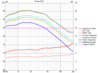
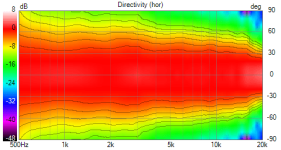
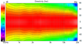
I had also tried with a smaller waveguide, less deep waveguide and 25mm rounding at edges. Here is the result for that
Device width x height = 376.00 x 324.00 mm (14.803 x 12.756")
Device length = 120.00 mm (4.724")


Next I will try out similar ideas as the ones tried out in limacon's thread..
Device width x height = 376.00 x 324.00 mm (14.803 x 12.756")
Device length = 120.00 mm (4.724")
Next I will try out similar ideas as the ones tried out in limacon's thread..
A simple way to look for where directivity features or issues are coming from is by looking at the off axis line curves rather than the polar heatmaps.
You should be able to see at what angle the frequency response is affected, and work out which part of the cabinet is causing the change. I also would not put too much effort in trying to fine the DI where 0.5 dB differences are seen, particularly with 3D meshes. The liklihood that all those tiny features make it through in real life to make the exact same curve is miniscule.
You should be able to see at what angle the frequency response is affected, and work out which part of the cabinet is causing the change. I also would not put too much effort in trying to fine the DI where 0.5 dB differences are seen, particularly with 3D meshes. The liklihood that all those tiny features make it through in real life to make the exact same curve is miniscule.
Also a 90 degree pattern waveguide will match up quite well with a big woofer at some range of frequencies lower down. To match a cardioid radiation the wall angle needs to be wider otherwise the difference in directivity between high and low frequencies will be large. Width, depth and wall angle are interelated, you can only pick two then the other is already set for you.
I have simulated a cardioid midrange using a 15" driver - https://www.diyaudio.com/community/...-design-the-easy-way-ath4.338806/post-7246372
DI around 8 dB around crossover frequency is perfectly fine in that case.
DI around 8 dB around crossover frequency is perfectly fine in that case.
I simulated a rounded cabinet of the same depth (310mm) as in the earlier case integrated with the waveguide..
It is hard to observe any differences between the results in the two cases.
Here are the results..
In all below results, the flattening of axial response has been done w.r.t 20 degrees off axis..
Device width x height = 376.00 x 324.00 mm (14.803 x 12.756")
Device length = 120.00 mm (4.724")
Regular cabinet with 25mm rounding and 310mm depth


Curved cabinet with 25mm rounding and 310mm depth


Side-by-side comparison between regular cabinet and curved cabinet (if at all it appears side by side in the browsers others are using.. 😀 )
Regular cabinet (left) Curved cabinet (right)


It is hard to observe any differences between the results in the two cases.
Here are the results..
In all below results, the flattening of axial response has been done w.r.t 20 degrees off axis..
Device width x height = 376.00 x 324.00 mm (14.803 x 12.756")
Device length = 120.00 mm (4.724")
Regular cabinet with 25mm rounding and 310mm depth
Curved cabinet with 25mm rounding and 310mm depth
Side-by-side comparison between regular cabinet and curved cabinet (if at all it appears side by side in the browsers others are using.. 😀 )
Regular cabinet (left) Curved cabinet (right)
Attachments
Yeah, it is a matter of the depth/width ratio, baffle-edge rounding and frequency. How I understand it it is all about how to reduce diffraction and back wave cancellation. The best results where received with a complex trapzoidal T-shape enclosure, if I remember correctly. But I don't know who did it.
Very nice comparison. The rounded back cabinet has a small effect... but it is significantly more difficult to construct.
Yeah the backside effects are mostly beyond 90deg off-axis. Sound would need to diffract all around the box to show up in the front, or any diffraction backwave from back corner so these are second or third order effects with greatly reduced amplitude, thus minimal effect in toward listening window. Sound expands outwards so the immediate surroundings of any transducer has most effect.
Also, the box seems to be wider than deep so there isn't that much to diffract from the back edge as sound that got there has relatively long wavelength. if you made the box narrow and deep you'd see more ripple below 90deg angles as well.
Also, the box seems to be wider than deep so there isn't that much to diffract from the back edge as sound that got there has relatively long wavelength. if you made the box narrow and deep you'd see more ripple below 90deg angles as well.
the rear of the cab does not matter much.
I optimised the waveguide for the box in the spk16 project. This made the directivity smoother and more constant below 3-4kHz.
I optimised the waveguide for the box in the spk16 project. This made the directivity smoother and more constant below 3-4kHz.
Yeah ~1db response wiggle is quite good already. There seems to be 0-axis hump around 1kHz, dip about 2kHz, another hump about 3kHz, so there is secondary sound source with roughly 17cm extra path length and opposite polarity, so it's the mouth that diffracts and sends the secondary soudn that makes the ripple by interfereing with direct sound.
The extra "slap-on" roundovers are not effective because curvature of the waveguide changes rapidly there, and diffracts. The roundover needs to be the same continuous curve as the main waveguide to avoid this.
edit. here simple example for continuous curve closed back very low diffraction waveguide https://www.diyaudio.com/community/...-design-the-easy-way-ath4.338806/post-7231463
I think there are some renders somewhere there for a hint what such thing looks like but the backside can be customized some without much problems in listening window. By backside I mean anything beyond the waveguide curve has made full 180deg freferenced to on-axis. As comparison the infinite baffle script and sim ends the curve at 90deg, so you need to continue to make a rollback to improve the mouth diffraction performance.
Basically, simulate a freestanding waveguide in ATH with t=1 setting, and then just enclose it as you wish, or even better try to imitate curve you get with t>1 to make it continuous much further. But as said you already have quite good performance.
Last edited:
I was curious about how it will all fit together to form a system.. Well at least in simulation land..😀
Here is a quick stitching of the MEH-waveguide described above without the curved cabinet and the dual 15inch woofer system with a sample crossover system implemented..
I have assumed that there will be one more cross between the mids on the MEH and the CD in it and it is not shown..
Another assumption is that the mids (closed back configuration) on the MEH waveguide will acquire whatever directivity the waveguide gives at lower frequencies


Directivity/horizontal polar pattern looks nice on paper/screen I think... 😀
Here is a quick stitching of the MEH-waveguide described above without the curved cabinet and the dual 15inch woofer system with a sample crossover system implemented..
I have assumed that there will be one more cross between the mids on the MEH and the CD in it and it is not shown..
Another assumption is that the mids (closed back configuration) on the MEH waveguide will acquire whatever directivity the waveguide gives at lower frequencies
Directivity/horizontal polar pattern looks nice on paper/screen I think... 😀
Last edited:
When the DI is 8 the pattern is no longer cardioid. When the lowest frequencies have a DI around 5dB and the high frequencies from waveguide sit at around 10dB the 5dB spread can still be accommodated but there is going to a big difference between how the speaker radiates at either end of the spectrum.I have simulated a cardioid midrange using a 15" driver - https://www.diyaudio.com/community/...-design-the-easy-way-ath4.338806/post-7246372
DI around 8 dB around crossover frequency is perfectly fine in that case.
I would aim to start setting the woofer level from the estimated in room response, have that be flat or slightly rising below 100Hz and adjust if it doesn't sound right.I was curious about how it will all fit together to form a system.. Well at least in simulation land
Agree with fluid. And also, for your music do you need to aim for flat in-room response to 30Hz? Does it help if you relax the requirements with F3 of ~40Hz and F10 of 32Hz? Most bass is between 50Hz and 200Hz...
It doesn't matter how we call it, that's why I showed the simulations. It could be called "utilized back radiation". Still, it is a significant improvement over a monopole, as illustrated in the data.When the DI is 8 the pattern is no longer cardioid. When the lowest frequencies have a DI around 5dB and the high frequencies from waveguide sit at around 10dB the 5dB spread can still be accommodated but there is going to a big difference between how the speaker radiates at either end of the spectrum.
I think it does. When there are accepted terms and they are used correctly communication is easy. When they are mixed up or taken to mean whatever anyone wants them to mean, there is confusion and wasted time replying back and forth like now...It doesn't matter how we call it
@fluid ,@tktran303 : Thanks for the suggestions about the speaker low end response shaping.. I don't think I often listen to music that has content down to 30Hz.. So I will try out as you mentioned.. Will adjust bass level based on in room response..
In the above prototype crossover, I didn't much focus on shaping the response in the very low end..
Anyway, my bass cabinets are not yet completed and has been delayed due to my friend (who is making the boxes for me) being unwell for some time now.. So I wait till the boxes are made and in the meanwhile work on top modules for it...
I think I will go with the above (relatively smaller sized waveguide in the simpler rectangular sort of box). Things to try out are the following..
1) Try tweaking the rounding around the waveguide to try and make it a continuous curve like @tmuikku mentioned.. (I don't know how to do this yet so need to check)
I also don't expect any big changes in the frequency response curves with just these changes.. but if at all some more smoothness comes around/above the 1kHz region, it is welcome.. Anyway I have to 3D print the waveguide. So shape doesn't matter however complicated the shape is.
2) I am guessing that the MEH configuration will/can cause more disruptions in the polars than all of what I have been seeing now.. I need to measure the polars of that prototype that I made to atleast start getting an idea about what all ghosts are waiting for me there.. 😀
Any term should have an agreed meaning.
“Misusing the term weakens that meaning, which makes the term less generally useful, because if someone uses that term then it no longer tells us anything useful. We have to dig in and figure out what they're actually talking about”
AI Researcher Simon Willison on Mark Zuckerberg’s “cultural vandalism” of the term ‘open source’ after the Facebook CEO claimed that Llama 3.1 405B, offered for download, is open source.
Ok, the weights can be adjusted, but it is NOT open source. Meta owns it. You provide your contact information and agree to their fair use policy to use it.
Where is integrity?
/rant off
So what is the correct term, if it is not a cardioid midrange enclosure (which, in the context of the thread, everyone understands, the more so when an example is shown to illustrate what is meant)?
- Home
- Loudspeakers
- Multi-Way
- A 3 way design study


