Happy to see someone actually trying it. This is a great work. If you succeed, this should become a big hit 🙂

Here is golden nugget for you:
Complex impedance data of 16mm melamine found here: https://www.sciencedirect.com/science/article/pii/S0003682X21001687?via=ihub
Turned into text file with VCAD curve tracer. Its not full bandwidth, but covers the important bandwidth for this application.
Put this into a datafile, like Melamine16.txt, include into the ABEC project, use alias Melamine16 for example:
In the solving script you already have WallImpedance part, something like this:
Impedance / damping is frequency dependent, so using static Value in the WallImpedance does not translate into reality. This complex impedance data should give you more accurate results with this particular damping material, which luckily seems to work quite nicely in passive cardioid application.
Please post your sims and measurements.
Complex impedance data of 16mm melamine found here: https://www.sciencedirect.com/science/article/pii/S0003682X21001687?via=ihub
Turned into text file with VCAD curve tracer. Its not full bandwidth, but covers the important bandwidth for this application.
Put this into a datafile, like Melamine16.txt, include into the ABEC project, use alias Melamine16 for example:
Code:
// Melamine foam normalized complex surface impedance, found it here:
// https://www.sciencedirect.com/science/article/pii/S0003682X21001687?via%3Dihub
Data_Format=Complex
Data_Domain=Frequency
    100        4.341    26.666
    150        2.876    20.083
    200        1.843    15.397
    400        1.087    7.596
    600        0.660    4.914
    1000    0.546    2.953
    1500    0.492    2.002
    2000    0.442    1.478
    2560    0.425    1.064
    3000    0.395    0.769
In the solving script you already have WallImpedance part, something like this:
Code:
WallImpedance "damping"
    RefElements="inside"
    ImpType=Impedance
//    Value=0.5
    DataFileAlias=Melamine16
    Normalized=true
Impedance / damping is frequency dependent, so using static Value in the WallImpedance does not translate into reality. This complex impedance data should give you more accurate results with this particular damping material, which luckily seems to work quite nicely in passive cardioid application.
Please post your sims and measurements.
Thanks for this data @tmuikku
I tried solving with above changes but the ABEC scripts tab says it is unable to link files related to damping.
Could you please try once?
I have attached the ATH-generated enclosure definition files (including the ABEC project) with this post.
I tried solving with above changes but the ABEC scripts tab says it is unable to link files related to damping.
Could you please try once?
I have attached the ATH-generated enclosure definition files (including the ABEC project) with this post.
Attachments
Hi,
in solving.txt change this:
WallImpedance
RefElements=SD1G1
ImpType=Damping
Value=0.5
to this:
WallImpedance
RefElements=SD1G1
ImpType=Impedance
DataFileAlias=Melamine16
Normalized=true
You also need to load the file into "Data files", right click Data files on ABEC Project tab, Add data-file Melamine16.txt and give it alias Melamine16
Yeah, basically the process is to make simulation and measurement and try to match them, which gives some confidence to rely design with simulation only. The cardioid pattern is kinda tricky to get working in a way that seemingly small changes (in real DUT and measurements) seem to affect the pattern a lot. Same goes for the sims, with its own quirks. For example the ImpType=Impedance doesn't seem to work if the material covers a hole but Admittance seems to get better match to reality. Can't load data on ImpType=Damping as you found out. The data is also hard to come by, would require impedance tube to make your own. Then, it takes some time to figure out the simulator, domains, normals, data, ABEC in general, million mesh files, 3D cad and so on. In short, took me quite lot of hours to get anywhere and still not there 😀
I've tried to match sim to reality on quite a complex model, and got close but not quite mainly because the damping. I'm having also another material within my box, for which I don't have the impedance data. And have been lazy not to build and measure with the melamine only to really nail on the simulation.
Things like magnet size, aperture size, internal volume, all change the results and its a lot of work to get sims match reality until hopefully someday they will and you can design a box in the simulator, but until then its a lot of work and uncertainty.
Based on this, if you want to get deep into it I would suggest to come up with some "simple" structure with the melamine foam playing a role, measure and simulate until match measurements. Build another / change the setup, and see if sims still matches. You could also try to find data for some other material and try with that as well. Lots of unknowns. Best resource for any ABEC related stuff is its help file, while some bits and bobs here on diyaudio.com, otherwise its just unexplored territory, which is fun, but heck of a lot of work 🙂 Not the typical "Google finds it" problem solving.
Last edited:
You are right @fluid 😀
I had expected that the measurements will look exactly like the simulations as it had happened with wavegudies. But this has given me a reality check... 🙂
I will try to do a little bit more experimentation to see where this goes and whether the results can be made little bit better. I have some melamine foam in hand I will use it in the cavity/cover the outsides of the cavity with it and see if something changes for the better.. I tried searching around for polyester wool (like akhotherm) but haven't got any yet.. I will update here once I get some results. 🙂
Yes try a half donut of melamine foam. Maybe 1cm depth of melamine, then use other material in the half donut gap between melamine and driver.
Vineeth you could route within one or two of your layer of xps to enable the driver's magnet to go through the hole then created. This way you could approach Mabat's initial gap value.
I'm not sure to be clear in my explanation, so take a look at how Kimmo did with the MTM section:
https://web.archive.org/web/20170425170846/http://kimmosaunisto.net/KS-585/KS-585.html#Prototypes
I agree with Mabat's you are onto something!
Ok, by half donut, i meant an horse shoe shape with a wall width of 1cm (or 1,6cm as you have data to simulate thank to Tmuikku) as a start. It's height equal to gap width ( stacking 1cm melamine's horseshoe slice).
By varying wall thickness you could taylor results.
The whole enchilada could be then glued and inserted into some fabric 'glove', as Kimmo use on the outside of his bigger box design, for neat finish.
By varying wall thickness you could taylor results.
The whole enchilada could be then glued and inserted into some fabric 'glove', as Kimmo use on the outside of his bigger box design, for neat finish.
Hi,
yeah there is some uncertainty to the melamine impedance data I posted, as I haven't made simple jig to measure reality and sims, and the relatively complex build I haven't been able to match exactly. The data seems plausible though, and probably much closer to reality than static 0.5 through whole spectrum, but still.
The complex simulation model I have has some error to it, like my driver frame/bulk is not modeled very accurately so some error might be there. I can vary sim results depending on how the ports are setup: where the domain interfaces are and which way the damping material normals are and so on. Also there might be something wrong in my measurements as they are the semi-anechoic livingroom measurements with ~4ms gate, so all the important stuff below 1kHz and resolution isn't optimal to say at least 🙂 Although the sim results seem plausible, its not the same as measurement results and I'm not sure if its the data or something else that is wrong. Hense simple jig to verify the data would be needed, I've been lazy and haven't done it yet 🙂
Last edited:
Thanks @krivium & @tmuikku 🙂
I did something very similar to what krivium mentioned. A pad of melamine foam directly behind the driver. A pad of foam below the driver in the slot But the thickness of it was 25mm instead of 16mm. I also thought that 16mm was not much effective at lower frequencies. So 25mm might help there. The other reason was that I was lazy to cut it even finer since the material i have came with that thickness.

Here are the next round of measurements with damping
My room height is about 290cm. The driver centre and mic height were at 132cm.
I was able to get a window size of about 5.1ms
Measurement set up

Following are the VituixCAD graphs

Comparison between ABEC simulations with 16mm damping for which tmuikku gave the impedance data

Measurements I got now with 25mm melamine foam

The latest iteration looks much better than before I think.. 😀
I did something very similar to what krivium mentioned. A pad of melamine foam directly behind the driver. A pad of foam below the driver in the slot But the thickness of it was 25mm instead of 16mm. I also thought that 16mm was not much effective at lower frequencies. So 25mm might help there. The other reason was that I was lazy to cut it even finer since the material i have came with that thickness.
Here are the next round of measurements with damping
My room height is about 290cm. The driver centre and mic height were at 132cm.
I was able to get a window size of about 5.1ms
Measurement set up
Following are the VituixCAD graphs
Comparison between ABEC simulations with 16mm damping for which tmuikku gave the impedance data
Measurements I got now with 25mm melamine foam
The latest iteration looks much better than before I think.. 😀
Attachments
If you have an impedance tube you could measure impedance for the actual material you have there 🙂 in the end, all that matters is the real results, not the sims.
The response is close to dipole below 500Hz or so, so there is no effect on the backwave on low frequencies. You could decrease size of the "aperture" with the melamine or with the blue material, increase volume of the backside "box", increase resistance by reducing open area on the back, use different material than melamine for more damping on low frequencies. Unscientifically all these would more or less affect low pass on the back and cause more (group) delay. Basically I'd try blocking the whole slot with the melamine foam, you could leave space inside but block it so there is no free path for sound other than through the melamine.
The response is close to dipole below 500Hz or so, so there is no effect on the backwave on low frequencies. You could decrease size of the "aperture" with the melamine or with the blue material, increase volume of the backside "box", increase resistance by reducing open area on the back, use different material than melamine for more damping on low frequencies. Unscientifically all these would more or less affect low pass on the back and cause more (group) delay. Basically I'd try blocking the whole slot with the melamine foam, you could leave space inside but block it so there is no free path for sound other than through the melamine.
Last edited:
@tmuikku: I don't have an impedance tube. Is it easy to make one? 😀
I am using this material for absorption (25mm thick)
https://www.auralexchange.com/product/nankarrow-proflat-4-nos-2ft-x-2ft-basotect-g-melamine-acoustic-foam/#:~:text=Nankarrow ProFlat™ acoustic foam,and ensures a quiet surrounding.
It is supposed to be Basotect G+ I think. They give the following graph on the page:

From the above graph, I think the absorption properties of the material is pretty bad below 1.5kHz..
I have some sheep wool material with me that is sort of pressed into sheets. Each sheet is 10mm thick.

I don't know if this will be better at damping than the melamine foam. 🤔
The simulations with 16mm melamine foam doesn't inspire much confidence regarding increasing the depth of the 'box'
Here is the polars with above damping material on a 300mm deep enclosure:

Same measurement with 170mm deep enclosure that I currently have:

There are only marginal differences and that too around 500 Hz to 1kHz.
So I probably have to manage things with the slot area & damping.
Now comparison between enlcosure of depth 170mm above damping material used in a 30mm deep slot vs 50mm deep slot (that I currently have)
30mm deep slot

50mm deep slot

Again, only marginal differences in the 500Hz to 1kHz region I think.
So that sort of narrows down my option to filling the slot with some damping material I think 🤔
I am using this material for absorption (25mm thick)
https://www.auralexchange.com/product/nankarrow-proflat-4-nos-2ft-x-2ft-basotect-g-melamine-acoustic-foam/#:~:text=Nankarrow ProFlat™ acoustic foam,and ensures a quiet surrounding.
It is supposed to be Basotect G+ I think. They give the following graph on the page:
From the above graph, I think the absorption properties of the material is pretty bad below 1.5kHz..
I have some sheep wool material with me that is sort of pressed into sheets. Each sheet is 10mm thick.
I don't know if this will be better at damping than the melamine foam. 🤔
The simulations with 16mm melamine foam doesn't inspire much confidence regarding increasing the depth of the 'box'
Here is the polars with above damping material on a 300mm deep enclosure:
Same measurement with 170mm deep enclosure that I currently have:
There are only marginal differences and that too around 500 Hz to 1kHz.
So I probably have to manage things with the slot area & damping.
Now comparison between enlcosure of depth 170mm above damping material used in a 30mm deep slot vs 50mm deep slot (that I currently have)
30mm deep slot
50mm deep slot
Again, only marginal differences in the 500Hz to 1kHz region I think.
So that sort of narrows down my option to filling the slot with some damping material I think 🤔
Ah yes, I mean internal volume of the "box", which is part of acoustic low pass filter that forms with the volume and aperture(s). Also the damping material adds resistance, basically a shelving filter as per the absorption coefficients you posted above. Both add group delay. The delay needs to relate to the distance of the aperture from front and so on.
The material is critical in a way that as you see from the absorption coefficients all of them have similar features, its roughly an S curve from no absorption on low frequencies to high absorption of ~1, which is 20db. Only difference is on which frequency the slope happens and how steep it is.
Apparently many of them work as on another thread people have been using anything from wool to basotect, I'm using melamine cleaning sponge I bought from local grocery store, which ought to be same stuff.
So, basically there is soup of variables that affect sound from the back side of the cone, mix them right and you have it, nice pattern 🙂 and it seems there are multiple combinations that work just fine. I'm not quite sure if I get it all right but I like to imagine it so that if you have too much acoustic low pass use worse absorption material. If you have too much absorption then do not use acoustic low pass. Then, one absolutely needs some damping material to tame resonances and smoothen things out, the material is probably something what you have access to, like the melamine foam, then all you can/need to do is adjust the apertures size and location to make the pattern happen. We also need some attenuation, some low passing for the backwave just due to match the response that bends around from the front. If you imagine you had ideal sound sources, one in opposite polarity, and they would be coaxial, all you need to do is to space them out and have equal amount of delay, also match their frequency responses at least to directions of interest, or something like this. Its a while as I played with it last time 🙂 In short, mate the damping material with the aperture size and position, or vice versa.
Also the outside dimensions of the enclosure affect pattern some, like size of the front panel, depth of the box and roundovers. Baffle size affects the delays some, but mainly its effects of diffraction.
Last edited:
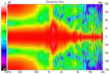
Seems like we are there at a fully cardioid response.. 😀 😀
Fully "filled" slot with melamine foam (2 x 25mm thick pieces filling the slot between baffle and the backside of enclosure)

VituixCAD responses:

The pic of the day

PS: There is some vibration of the entire measurement assembly & the prottoype at a very narrow frequency range. I could hear this while measuring. That resonance's impact might be there somewhere in the frequency responses.
It would go away with a proper construction I think... 🙂
Very exciting results though.. 😀
Fully "filled" slot with melamine foam (2 x 25mm thick pieces filling the slot between baffle and the backside of enclosure)
VituixCAD responses:
The pic of the day
PS: There is some vibration of the entire measurement assembly & the prottoype at a very narrow frequency range. I could hear this while measuring. That resonance's impact might be there somewhere in the frequency responses.
It would go away with a proper construction I think... 🙂
Very exciting results though.. 😀
No, it's not at all my idea. Perhaps the implementation, but this is truly your practical solution. I admire that.
Passive cardioid with attenuated side slots was one of kimmosto's challenges about 10-15 years ago. Baffle width, internal panels, slots' dimensions and damping all are important variables. D&D developer keysir reported his experiments here at diyaudio.
Lowest bass has same loss as dipole, as we can see in Vineeth's measurements happening below 500Hz. A coaxial unit seems to do pretty well in matching patterns! Just add bass unit below 200Hz.
Here is my SEAS MR18 in IKEA Blanda bowl ball with backside opening, eq'd and without bass module. https://www.diyaudio.com/community/threads/seas-mr18-3-way.322839/
.png")
Lowest bass has same loss as dipole, as we can see in Vineeth's measurements happening below 500Hz. A coaxial unit seems to do pretty well in matching patterns! Just add bass unit below 200Hz.
Here is my SEAS MR18 in IKEA Blanda bowl ball with backside opening, eq'd and without bass module. https://www.diyaudio.com/community/threads/seas-mr18-3-way.322839/
Last edited:
In fact (and it's often overlooked), at 500 Hz there can still be several dB of on-axis gain, compared to a closed enclosure, as the radiation from the port sums constructively with the front-radiated sound:Lowest bass has same loss as dipole, as we can see in Vineeth's measurements happening below 500Hz.
https://www.diyaudio.com/community/threads/a-3-way-design-study.376620/post-7334585
I'm actually pretty curious what's the gain here. That should be obvious when compared with a (known) tweeter response.
Around 1 kHz I would expect a half-space sensitivity of the midwoofer.
Last edited:
It would be interesting to see it with the port blocked/covered, i.e. with the rear chamber effectively closed, e.g. with another inserted xps panels, even if on-axis only (basically to get the above graph).
- Home
- Loudspeakers
- Multi-Way
- A 3 way design study