Quick thoughts for the application: The cardioid pattern is not very useful for the table reflection, as the angle is quite small ~50deg so attenuation isn't that much towards it, only few db. Main benefit from the cardioid pattern would be some reduction in sound towards wall behind the speaker (and side walls in the room somewhere). If the wall is 40cm behind the speaker front, it has double distance of sound travel than direct sound if listened 40cm away, which is already 6db of attenuation, assuming its far field enough. For this reason I'm thinkin audible effect of the pattern isn't that much but I hope its worth it 🙂 You might already like the small leaky box sound regardless.
Last edited:

I think it was this [mm]:@mabat: Could you please let me know the dimensions of the slot you used in the above simulation for 5-inch driver?
I made this much of the carioid box prototype. 😀

Basically, the Sica coax in a 50mm thick xps foam baffle. I am planning to leave the 30mm gap behind the driver and stack pieces like above at the back of the gap for this experiment.. 🙂 I probably also need ro round the edges around the driver too.. All that I need to do after I recover from the current Covid infection.. 🙂
Basically, the Sica coax in a 50mm thick xps foam baffle. I am planning to leave the 30mm gap behind the driver and stack pieces like above at the back of the gap for this experiment.. 🙂 I probably also need ro round the edges around the driver too.. All that I need to do after I recover from the current Covid infection.. 🙂
Would anyone still have the measurement files for the Sica coax in a teardrop enclosure? The Google link seems to have expired 🙂
Thanks, works great. I wanted to see if the teardrop shape was more suitable for active cardioid than a traditional box enclosure. Seems like it is a lot better, but still far from ideal. Here's a quick attempt where the rear woofer also handles the bass output. This of course assumes a symmetrical enclosure which the teardrop is not

I completed the xps foam prototype, attached the Sica coax driver to it & made some measurements. 🙂
All is not good though... Here is the pic of the measurement set-up. The front baffle is 50mm thick. However, I couldn't keep the slot width at 30mm (as shown above in Mabat's original design) due to the wires connected to the tweeter being at the back of the driver as seen in the pic. It was getting crushed at 30mm. So I increased the slot width to 50mm. Behind the slot, there is a 75mm thick part of the 'box'.
All the panels were glued together well. I just used some red colour tape to wrap around the whole cabinet just for extra protection.

The mic is 110cm away from the baffle. I used a gate window of 4.65ms, and here is how the measurements looked for the mid-driver. I took only horizontal plane measurements from 0 degrees to 180 degrees.

It looks like there is a weird resonance around 1.5 kHz or so. Other than that, my measurements probably lack much resolution below 1kHz. Still, some kind of dipole (??) pattern emerges below 1kHz.
Here is how the tweeter measurements looked like (I decreased 5dB of signal power on the tweeter compared to the mid)

This one looks familar and is similar to previous measurements that I had taken of the same tweeter in the teardrop-shaped enclosure (except for how it looks around 600Hz). It sort of tells that the measurement setup I have may not be very bad.
Anyway, I think something is wrong with my construction of the box or this driver or a combination of both. 🙁
I have no idea at the moment about what went wrong🙄
All is not good though... Here is the pic of the measurement set-up. The front baffle is 50mm thick. However, I couldn't keep the slot width at 30mm (as shown above in Mabat's original design) due to the wires connected to the tweeter being at the back of the driver as seen in the pic. It was getting crushed at 30mm. So I increased the slot width to 50mm. Behind the slot, there is a 75mm thick part of the 'box'.
All the panels were glued together well. I just used some red colour tape to wrap around the whole cabinet just for extra protection.
The mic is 110cm away from the baffle. I used a gate window of 4.65ms, and here is how the measurements looked for the mid-driver. I took only horizontal plane measurements from 0 degrees to 180 degrees.
It looks like there is a weird resonance around 1.5 kHz or so. Other than that, my measurements probably lack much resolution below 1kHz. Still, some kind of dipole (??) pattern emerges below 1kHz.
Here is how the tweeter measurements looked like (I decreased 5dB of signal power on the tweeter compared to the mid)
This one looks familar and is similar to previous measurements that I had taken of the same tweeter in the teardrop-shaped enclosure (except for how it looks around 600Hz). It sort of tells that the measurement setup I have may not be very bad.
Anyway, I think something is wrong with my construction of the box or this driver or a combination of both. 🙁
I have no idea at the moment about what went wrong🙄
Attachments
Last edited:
Some images of directivity transition and polar pattern change from Dipole 'ish' to cardioid 'ish', I guess


Thinking about this more and more, I think the slot (at the back of the driver) area vs driver membrane area might heavily influence the dipole-cardioid transition region & radiation pattern formation.
I think Mabat simulated a driver with area 120cm^2. My driver Sd is 78.5 cm^2.
In Mabat's sim, the slot width was 30cm. In my prototype, it was 50cm.
The larger area/volume at the back might make the driver behave like a dipole in some frequency ranges, especially at low frequencies, I guess.. 🤔
I think Mabat simulated a driver with area 120cm^2. My driver Sd is 78.5 cm^2.
In Mabat's sim, the slot width was 30cm. In my prototype, it was 50cm.
The larger area/volume at the back might make the driver behave like a dipole in some frequency ranges, especially at low frequencies, I guess.. 🤔
In fact I think that's pretty promising. Remember that it also takes some additional acoustic damping to work as expected - that was the big unknown during the simulations, how to practically achieve that, as that was something not possible to simulate easily.
This is the "BEE" code I used (I believe). If you want, you can try different dimensions:
The latest Ath is probably required: https://at-horns.eu/ext/ath-4.9.0-pre-230122-2.zip
Code:
R-OSSE = {
  R = 130.0
  r0 = 12.7
  a0 = 7.5
  a = 39
  k = 1.2
  r = 0.3
  b = 0.3
  m = 0.8
  q = 3.7
}
Rot = 3

; LF enclosure
BEE = {
  Height = 500      ; [mm]
  Radius = 80      ; [mm]
  Depth = 250       ; [mm]
  Source = 50       ; diaphragm radius [mm]
  YOffset = -80       ; [mm]
  ZOffset = 40      ; [mm]
  ; mesh resolution: top-front, top-back, bottom-back, bottom-front
  Resolution = 20,30,40,40

  ; dipole opening
  Port = {
    z = 50          ; [mm]
    w = 30          ; [mm]
    wt = 15         ; wall thickness [mm]
    Resolution = 20 ; [mm]
    Damping = 0.5   ; interior wall damping
    OpenTop = 1
  }
}

ABEC.SimType = 2
ABEC.MeshFrequency = 1000
ABEC.NumFrequencies = 40
ABEC.Abscissa = 1
ABEC.f1 = 50
ABEC.f2 = 4000

; don't mesh the waveguide
Mesh.WG = 0

Mesh.LengthSegments = 12
Mesh.AngularSegments = 64
Mesh.SubdomainSlices =
Mesh.WallThickness = 5

;Mesh.VerticalOffset = 260
Mesh.ThroatResolution = 15
Mesh.MouthResolution = 20
Mesh.RearResolution = 20
Mesh.Quadrants = 14

ABEC.Polars:SPL_H = {
  MapAngleRange = 0,180,3
  NormAngle = 0
  Distance = 2
}

ABEC.Polars:SPL_V = {
  MapAngleRange = -180,180,72
  NormAngle = 0
  Distance = 2
  Inclination = 270
}

Output.ABECProject = 1
Output.STL = 0

Report = {
  PolarData = SPL_H
  GnuplotCode = 2x2nlf.gpl
  Title = BEE0
  Width = 1600
  Height = 900
  MaxAnglePM = 180
}You forgot to calibrate your expectations 🙂I have no idea at the moment about what went wrong🙄
You are right @fluid 😀
I had expected that the measurements will look exactly like the simulations as it had happened with wavegudies. But this has given me a reality check... 🙂
I will try to do a little bit more experimentation to see where this goes and whether the results can be made little bit better. I have some melamine foam in hand I will use it in the cavity/cover the outsides of the cavity with it and see if something changes for the better.. I tried searching around for polyester wool (like akhotherm) but haven't got any yet.. I will update here once I get some results. 🙂
Understandable but a generic damping value applied to a surface needs empirical validation to understand the limits of it's usability.I had expected that the measurements will look exactly like the simulations as it had happened with wavegudies. But this has given me a reality check... 🙂
Using some damping material in the gap will make it less dipole. Look at the Linkwitz LX Mini.I will try to do a little bit more experimentation to see where this goes and whether the results can be made little bit better.
Thanks @fluid 🙂 I will read and try it out
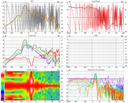
In the meanwhile, I ran the ABEC project generated by ATH with my modified enclosure and slot dimensions with no damping.
It looked like this:


What I got in VituixCAD with actual measurements yesterday

There definitely is some similarity... 😀 😀 This is exciting
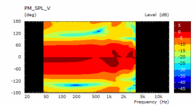
Now I will try damping of 0.5 in the model next. This is how it looks like:

The results look like this in simulation

Looks neat... 😀
But whether this will match with reality, I will have to measure and see next.. 🙂
In the meanwhile, I ran the ABEC project generated by ATH with my modified enclosure and slot dimensions with no damping.
It looked like this:
What I got in VituixCAD with actual measurements yesterday
There definitely is some similarity... 😀 😀 This is exciting
Now I will try damping of 0.5 in the model next. This is how it looks like:
The results look like this in simulation
Looks neat... 😀
But whether this will match with reality, I will have to measure and see next.. 🙂
Attachments
- Home
- Loudspeakers
- Multi-Way
- A 3 way design study