Looking at the measurements I thought "wow, what DIY Coax is this, looks like a KEF!".
Then I enlarged the picture ... 🤓
Which chassis did you use, what speaker did you butcher?

@IamJF
I think it's the sica 5.5 inch:
https://www.diyaudio.com/community/threads/a-3-way-design-study.376620/post-7332964
Edit and thanks @vineethkumar01 - sorry, i did not realize you were speaking of different speakers!
I think it's the sica 5.5 inch:
https://www.diyaudio.com/community/threads/a-3-way-design-study.376620/post-7332964
Edit and thanks @vineethkumar01 - sorry, i did not realize you were speaking of different speakers!
Last edited:
@stv: My build uses the Sica 5.5inch coax. But @tktran303 uses the KEF itself I think, from the pics..
A crossover making exercise using linear phase filters 😀


I have updated the latest project files here if anyone wants to take a look
https://drive.google.com/file/d/1a7JggO4WGSuuGhyxZxYnpzWRJGMYqD3h/view?usp=sharing
I have updated the latest project files here if anyone wants to take a look
https://drive.google.com/file/d/1a7JggO4WGSuuGhyxZxYnpzWRJGMYqD3h/view?usp=sharing
It might be just me, but the peaking in the 400-500 Hz range to me would not be desirable. Otherwise, this looks very very good.
Looking at the measurements I thought "wow, what DIY Coax is this, looks like a KEF!".
Then I enlarged the picture ... 🤓
Which chassis did you use, what speaker did you butcher?
Haven't you noticed Tktran303 just started a thread which should give a hint.
😉
Peaking at 4-500Hz might be a measurement artefact, if simulation is done per IRL measurements.
I'd love to hear your impressions of the minimum phase/minimum latency crossover differences. I feel like I can hear the 'flips' in big multiway systems sometimes. Not often in music, but more so when there's a slide on a stringed instrument or an electronic track. It's practically screaming at me during sine wave sweeps for room correction.
yes, that could be true. With the standard process of merging near field and gated (4 - 8 ms) far field measurements, combined with a calculated/simulated baffle diffraction, results in some measurement uncertainty. The maximum measurement uncertainty is usually in the 200 - 600 Hz range. In this range, the NF response is highly influenced by diffraction simulation, and the far field response has low resolution due to the gating.Peaking at 4-500Hz might be a measurement artefact, if simulation is done per IRL measurements.
Fortunately for all of us, this is a region where ground plane measurements really shine. With a 15 ms gate, we get good resolution down to 200 Hz. With a ground plane measurement, 15 ms is sometimes possible in a large room. Or outdoors we need just a small flat area.
It is also possible to judge this region subjectively by ear. If there is a peaking at 500 Hz, he will know it soon enough...
@hifijim ,@wolf_teeth, Can you help me by pointing out the 400-500Hz bump? Is it the 1 dB bump in on axis response around that region, after crossover?
I think I might have to try a ground plane measurement as well next time I get a chance to measure.
Also, I realized that the c-c spacing of the drivers is 23cm which is less than 28cm (1/4th wavelength at the 300Hz crossover). So can this speaker be called a point source speaker? 😀
I think I might have to try a ground plane measurement as well next time I get a chance to measure.
Also, I realized that the c-c spacing of the drivers is 23cm which is less than 28cm (1/4th wavelength at the 300Hz crossover). So can this speaker be called a point source speaker? 😀
Between 100 and 1K there is a 1dB rise up and fall down peaking at 350Hz. The woofer crossover shelves out adding a little bit more output throught that region. The really deep null in the native woofer response at 1K is a little strange too.
Thanks @fluid.
Now I understand. I will take a look at the woofer curves again. The woofer shelving out later in its slope down area looks a little strange.
I think the 1kHz deep dip has something to do with the big surround of this subwoofer driver ( Wavecor SW 215) The company data sheet shows this.


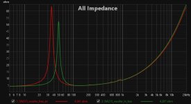
My impedance measurements and neafield for the driver in box looks like this (before baffle step adjustment)

and the polars before merging with nearfield like below. I suspect the very low frequency resolution and the window effects in the low frequency region is contributing to the wiggles as well. Also there are resonance around 200Hz, 600Hz, and 900Hz. 200Hz one seems to have minimal effect but the other two have more effect

Now I understand. I will take a look at the woofer curves again. The woofer shelving out later in its slope down area looks a little strange.
I think the 1kHz deep dip has something to do with the big surround of this subwoofer driver ( Wavecor SW 215) The company data sheet shows this.
My impedance measurements and neafield for the driver in box looks like this (before baffle step adjustment)
and the polars before merging with nearfield like below. I suspect the very low frequency resolution and the window effects in the low frequency region is contributing to the wiggles as well. Also there are resonance around 200Hz, 600Hz, and 900Hz. 200Hz one seems to have minimal effect but the other two have more effect
Attachments
The overall +1 dB rise running from 200 - 800 Hz... as @fluid pointed out. This is the kind of thing which is usually taken care of during the subjective voicing process... It is really hard to judge the impact of 1 dB humps by examining a frequency response plot... it may be a non issue. Room positioning will have a substantial impact on this also. So even if this is NOT an measurement anomaly, it may have no sonic impact.Can you help me by pointing out the 400-500Hz bump?
Generally, my preferred frequency balance is to have the maximum at 50-100 Hz, and then a very gently downward slope from 100 Hz to 10k, and then flat above 10k.
Overall your project looks really great so far.
hifijim +1, NF+FF merging process is not exact (especially matching NF level to FF level where both overlap in broad frequency area, at least they should, but often it is not the case so one has to decide by the feeling, so +-1dB NF/FF level mismatch can occur), same goes for gated measurements with ~4-5ms window. So this all, especially for 3way with lower crossover ~300Hz, is a guess. One should do the procedure as precise as he can, but must be aware of the weaknesses of the method, and make crossover adjustment based on subjective evaluation.
Have you been able to listen to it? I think that may be one of the most important goals with these type of projects 😀.
Even if you have only one ready for action, mono listening should give you a very good impression of the balance of the speaker.
Stereo listening (and listening pleasure) depends on much more factors. Drag one speaker out into the middle of the room and press play.
Move around a bit and judge it's overall balance. Happy? (make sure to make the source music mono too, also spend some time listening to spoken word/talking).
Try not to let these guys get into your head……..people that can perceive a 1db differential with confidence are 1 in a thousand and 1 in 20 that can do the same for 2db. Add in complex harmonic content in a 3D space and your 1.5db rise is irrelevant.
Maybe you decide to listen with a sweater on at times…..so the reflected energy from your shoulder in a passband is attenuated 1-2db or so…..or that listener happens to have variations in his outer ear shape and size?…….or is there a reference for clothing and ear size?
And if you start to consider the mastering engineer may have applied a 2-3db low Q cut filter to the midbass region (EXTREMELY TYPICAL PRACTICE) to reduce vocal and string resonance…..well…..you get the point.…..you folks are chasing a theoretical reference that will remain snake oil as long as folks continue to have genetic variance.
I think it’s important to reflect on your individual DIY mission statement…..whatever that may be. It’s nice to share your work but at the end of the day, the work is an expression of your desire, skill and purpose. Heck 90% of a speaker’s performance is judged on first looks before a single volt passes through its coils…..and most here and on other forums will never experience your work first hand. And always….always ask the question..….should I or could I?
Broad band 1dB rise ... that's not too hard to hear in an AB comparison. And for sure WAY more people can hear that (in fact that's a basic ability of the ear. Like hearing down to 0dBSpl)Try not to let these guys get into your head……..people that can perceive a 1db differential with confidence are 1 in a thousand
But in this project ... having this area a little higher is probably good. Give it a listen!
There is always a listening check and tuning after getting the first 95% perfectly right ... 😉
Then decide what to do. Could be that the speaker sounds "strange" flat on axis cause of the directivity to lower frequencies what we are not used to. Like my speaker with 2" midrange - flat on axis always was to much mids. Dialed it back 1-1,5dB and everything was perfect.
I would say ampere passes through the coil ... 🤓single volt passes through its coils
I'm with @IamJF here. A broadband 1dB rise will change the spectral tilt of the entire speaker. It is enough for me to want to unpad the mid and tweeter a bit if left that way, and if the measurements are reality. If it is just a splicing anomaly et al, then it may not be present as described.
The +2dB@240Hz in the woofer xover for that matter is likely debatable for the same reason, and likely may not be needed. I think this is what is causing the issue in the on axis response.
We really are splitting hairs here, but as far as hair goes here, you want it rather controlled and not unkempt.
All great comments, and some truth in all.
I would add that the room comes into play. As does your listening material. What sounds too hot on the top end or not enough on the bottom end. Well, changing tracks may change that opinion.
One thing I will add, if I may, about these coaxial speakers, (and wave-guided tweeter speakers as well) is to experiment with over toe-in
Suppose you are listening listen to just ONE test speaker. Put it where you might normally place your left speaker. Now turn/rotate this speaker so that the on-axis points at your opposite shoulder, when you are seated in the main listening position.
So your left speaker would be pointed directly as your right shoulder, and your right speaker would be pointed at your left shoulder. To be clear, If you had two speakers, and your were sitting at the listening position, then the speakers would be rotated so that the on-axis would meet at a point IN FRONT of your main listening position.
Very few people tend to try this over toe technique. And of course it doesn’t replace rational design decisions. You design may be good, in part, due to the DIY effect , but there’s good science why this can be the icing on your cake.
What this does is to reduce the impact of early reflections. Near off-axis angles are sent almost completely at the listening position and much less towards the side walls. It's only the far off-axis that really get to bounce from the walls and this should improve the stereo image stability.
So with constant directivity speakers, instead of having a single seat as the the sweet spot, the listening area just widened considerably, so that the entire couch is the sweet spot.
I do not find that the sweet spot is so narrow with my Monoculus design. I did play with toe-in a lot, and found the best to be angled just outside my typical toe-in where the speaker faces me, maybe 5 degrees if that. I can sit anywhere on the couch and get the same effects. The imaging and Soundstage portrays larger field than just the speakers, with things in the mix clearly being outside of both left and right positions. It's just surreal.
- Home
- Loudspeakers
- Multi-Way
- A 3 way design study