So the speaker is alive.. 😀
I tested this crossover


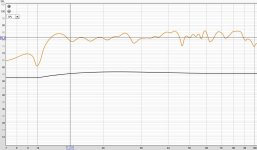
Here is the reference axis (20 degrees off axis) measurement I made of the speaker from 50 inches away.
It is almost exactly as per the predicted response in VituixCAD.
The blue line is what I took as the reference based on Vituixcad

So far I like it a lot.. But honeymoon days.. 😀 Need to listen a lot more.. But the vocals sound very open is the first feeling I got.
I am missing a bit of bass that I am used to with my big speakers but maybe more tuning needed.. 🙂 More updates in coming days as I listen more
If anyone is wondering how the speaker loos like (sounds like 😉 ) while it is singing, see the below video 😛
I tested this crossover
Here is the reference axis (20 degrees off axis) measurement I made of the speaker from 50 inches away.
It is almost exactly as per the predicted response in VituixCAD.
The blue line is what I took as the reference based on Vituixcad
So far I like it a lot.. But honeymoon days.. 😀 Need to listen a lot more.. But the vocals sound very open is the first feeling I got.
I am missing a bit of bass that I am used to with my big speakers but maybe more tuning needed.. 🙂 More updates in coming days as I listen more
If anyone is wondering how the speaker loos like (sounds like 😉 ) while it is singing, see the below video 😛

The dip at 100hz is probably wall behind speakers reflection. You have a major standing wave peak and null at 32hz and 40 ish Hz.
For best sounding bass you should target within +-5db with entire bass range. Anything above 100hz should be taken care by moderate treatment/minimal eq. But I see your bass response rolls off earlier. I target flat down to 10hz with my main gear even for music with minimal eq.(see attached)
Do you have time domain response?
Yes I can hear that boom sound in video due lack of treatment which I had too two years back. And this is even with your bass peaks below your flatline. Imagine how it would feel with flat bass response target.
What did you use to record sound? Measurement/smartphone mics are limited in dynamic range.
I have a rode m5 matched pair used to record my instruments. Let me see if I can get to record my floorstanders and upload on my channel once my current mods/upgrades are done. You will be able to gauge the difference with how bass should sound even with these samples. Slick and fast.
Attachments
Also in a untreated room flat response may not be the best response as bad/stray energy builds up especially with repetitive passages like music. Thats why movie always seem to sound better than music in a untreated room because movies are more dynamic in nature than music which is just repetitive energy causing build up.
very excellent result. It is comforting when measured reality matches simulation so well.It is almost exactly as per the predicted response in VituixCAD.
Also, recently my 6 channel audio interface, which I use for DSP crossover has been showing some issues in 2 of its output channels. I am seeing a constant 3rd harmonic distortion of 2 percent across the full bandwidth from 20Hz to 20kHz+. So it seems like either I might have to go with another DSP solution or use only 4 channels to drive the bass and mid+tweeter with a passive crossover between mid and tweeter. I have to think about this and find a solution (though I am gravitating more towards a full DSP solution).
The option I use is a PC with video card HDMI output to a used home theater receiver (HTR). Each channel from the HTR is connected to a single driver. Then I use Equalizer APO to control each channel output. For example, my two-way left stereo speaker is amplified by two separate outputs from the HTR: tweeter powered by the Left HTR output, woofer powered by the Side Left HTR output. You can create crossovers, equalization, delays, etc in Equalizer APO. However, I recently started using VituixCAD to create transfer files instead.
General Overview
I start by using VituixCAD to flatten each driver from my imported measurements on whatever listening axis I want using the Optimizer - in this case 10 degrees. Short all the blocks except the transfer file G(f). Then I choose the block and open the Optimizer to create the transfer files with the settings I want.


After that's done I remove the shorts from the blocks and set up my crossovers. Then I create the transfer files using Impulse response under the View tab, leaving any shorted bocks I don't want in my transfer files.


I confirm my Windows Sound settings are set up correctly for surround and match the sample rate of the transfer files (WAV) I exported in VituixCAD. If the sample rates don't match Equalizer APO will reject the files. I also make sure my surround speakers are set to full range in Windows.


I cut and paste the transfer (WAV) files from the VituixCAD directory into the EqualizerAPO "config" folder. Write a E-APO file for each crossover I want to compare, then use the E-APO editor to switch between them. The changes happen immediately so you can test the same sections of music or movie soundtracks against crossover options.


I've attached two PDFs with complete instructions written by Reid Towsley.
Attachments
Vineethkumar01,
Might i suggest something for your next recording?
Could you bring the loudspeaker more into the room and then move around slowly to give an idea of the cardioid directivity at play?
Same as in this ( from TimVG's in ASR directiva cardioid related thread):
Might i suggest something for your next recording?
Could you bring the loudspeaker more into the room and then move around slowly to give an idea of the cardioid directivity at play?
Same as in this ( from TimVG's in ASR directiva cardioid related thread):
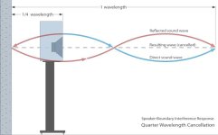
One experiment you can do to take care of that 100hz null is moving the speakers slightly forward from wall behind so that the null is glided towards one of those peaks between 100hz and 200hz and they cancel out each other. Of course this will work if my suspect is right and also cause of those peaks is not again due to same interference.
Or else I would generally move further forward so that null moves towards 200hz territory where it is easy to tame the boundary interference with treatment. You can calculate by matching quarter wavelength distance of 200hz with distance to wall behind from speakers.
Another way is ofcourse is play around with delays without physically moving around which I don't since I don't prefer to use dsp on fronts.
Edit: here's the illustration if I was not clear.
Attachments
Last edited:
Vineeth images can be deceptive, but it looks like the speaker might be positioned a similar distance away from the wall as the woofer is from the floor. If this is so, it will cause the interference to be worse, 86cm is a bad distance for 100Hz, speakers are better closer to a wall or further away, 1m is generally a bad distance for bass. The advice of pulling your speakers away from the wall can be just as misleading as getting the drivers closer together 🙂 It might be true, or it might be worse, depending on the circumstances.
Of course images/graphs are just for theory reference. In a room lots of things happen. In fact treatment/placements can make things look worse in the frequency domain after treatment as one issue might be hiding behind another. But you always see the benefits of treatment in time domain and also in hearing.
I listened to the speakers even more today. I like it more and more. Pulled it about 1m away (drivers 1.35 m) from the walls. It sounded even better than yesterday 🙂
I feel that there is really something magical with the vocals and highs on this speaker. But the bass region needs a bit of tuning, probably the lower crossover between mid and bass too.. Also, I felt like the sound of some instruments like the bass guitar and low notes on piano are not very well defined like I am used to with my bigger speakers. Maybe another version of the crossover might help me identify things better regarding the influence of that bass-mid crossover on all this. Maybe the room and placement also had something to do with this
Here are some more plots which I got when I took the measurement yesterday to confirm if the crossover is working fine.
These may slightly change once I fix the final position of the speakers around the PC and take measurements from MLP.
During yesterday's measurement. My computer's CPU was about 90cm away at 90 degrees to baffle plane the speaker. I suspect this might have also had some effect on the graphs.
The ETC curve (from measurement position 1.2m away from the speakers)

Wavelet spectrogram

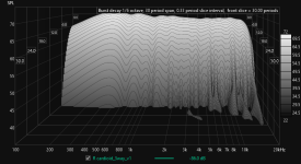
Burst decay (40dB dynamic range on y axis)

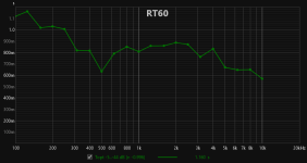
Though I dont know if it is of any use in an application like this, here is the EDT curve from RT60 tab

@fluid: Thanks for the suggestions.. I will experiment with final placement and closeness to walls when both the speakers are ready and take all measurements from MLP once again. When I measured the speakers yesterday, the drivers were about 65cm in front of the back wall. The woofer was about 96cm up from the floor. The minimum distance of the front driver away from the walls is about 36cm (due to the depth of the cabinet). I will try this placement first
@hifijim: Thanks for your encouragement. 🙂
Words like yours are what often keeps me motivated to push forward with these kind of projects and keep learning more about all this. 🙂
@krevilplays: Thanks for the suggestions.. but regarding the importance of placement & room treatment, you might be preaching to the choir here 🙂
My objective in yesterday's measurement session was only to see if the crossover was working as expected. I did not even look at what is happening to the bass. From what I can tell, looking at gated measurements & ungated ones, the crossover is working well. I have not even thought about the room/placement related EQing yet. That will done hopefully in the coming days & weeks. As I have said earlier, I have some limitations w.r.t room treatment here, So I will try to use 2 of my 8 foot tall and 8inch thick acoustic absorption panels somewhere, and see if it is of any use. Beyond that, room treatment-wise, I am helpless 🙂
Gated measurement at 4.25ms gate window (I am also not looking for an ultra flat response with this crossover. There is a slope down of about 2dB/decade with this one)


For reference, this is what VituixCAD predicted for the reference axis step response

@CinnamonRolls: Thanks a lot for sharing your workflow with FIR filter generation 🙂 In fact I use almost the exact same method with VituixCAD, EQApo and my 6 channel soundcard. I haven't used the response flattening filters generated by VituixCAD in the last one year because initially when I used it, I felt something was wrong. Maybe I didn't dial it in properly at the time.. I will try it again.
I feel that there is really something magical with the vocals and highs on this speaker. But the bass region needs a bit of tuning, probably the lower crossover between mid and bass too.. Also, I felt like the sound of some instruments like the bass guitar and low notes on piano are not very well defined like I am used to with my bigger speakers. Maybe another version of the crossover might help me identify things better regarding the influence of that bass-mid crossover on all this. Maybe the room and placement also had something to do with this
Here are some more plots which I got when I took the measurement yesterday to confirm if the crossover is working fine.
These may slightly change once I fix the final position of the speakers around the PC and take measurements from MLP.
During yesterday's measurement. My computer's CPU was about 90cm away at 90 degrees to baffle plane the speaker. I suspect this might have also had some effect on the graphs.
The ETC curve (from measurement position 1.2m away from the speakers)
Wavelet spectrogram
Burst decay (40dB dynamic range on y axis)
Though I dont know if it is of any use in an application like this, here is the EDT curve from RT60 tab
@fluid: Thanks for the suggestions.. I will experiment with final placement and closeness to walls when both the speakers are ready and take all measurements from MLP once again. When I measured the speakers yesterday, the drivers were about 65cm in front of the back wall. The woofer was about 96cm up from the floor. The minimum distance of the front driver away from the walls is about 36cm (due to the depth of the cabinet). I will try this placement first
@hifijim: Thanks for your encouragement. 🙂
Words like yours are what often keeps me motivated to push forward with these kind of projects and keep learning more about all this. 🙂
@krevilplays: Thanks for the suggestions.. but regarding the importance of placement & room treatment, you might be preaching to the choir here 🙂
My objective in yesterday's measurement session was only to see if the crossover was working as expected. I did not even look at what is happening to the bass. From what I can tell, looking at gated measurements & ungated ones, the crossover is working well. I have not even thought about the room/placement related EQing yet. That will done hopefully in the coming days & weeks. As I have said earlier, I have some limitations w.r.t room treatment here, So I will try to use 2 of my 8 foot tall and 8inch thick acoustic absorption panels somewhere, and see if it is of any use. Beyond that, room treatment-wise, I am helpless 🙂
Gated measurement at 4.25ms gate window (I am also not looking for an ultra flat response with this crossover. There is a slope down of about 2dB/decade with this one)
For reference, this is what VituixCAD predicted for the reference axis step response
@CinnamonRolls: Thanks a lot for sharing your workflow with FIR filter generation 🙂 In fact I use almost the exact same method with VituixCAD, EQApo and my 6 channel soundcard. I haven't used the response flattening filters generated by VituixCAD in the last one year because initially when I used it, I felt something was wrong. Maybe I didn't dial it in properly at the time.. I will try it again.
Attachments

Inversion EQ of that type makes for straight graphs but rarely good sounding speakers.Maybe I didn't dial it in properly at the time..
I am missing a bit of bass that I am used to with my big speakers but maybe more tuning needed..
I guess all it needs now is a few more woofers below for it to be an excellent full range type of speaker 😉.
I particularly like the horizontal/vertical pattern control.
Fair enough. In the end it's our own satisfaction with sound that we seek that matters. Good that you are happy with sound you have so far. Probably was too much eager to sharing my experience soon as I would be busy with my next project coming weeks. Hope it was of some use. Cheers! All the very best.
"I am also not looking for an ultra flat response with this crossover"
Well that is still flat response to my ears. If somebody looks at my custom curve it sure will raise few eyebrows. But takes care of long hours of listening without fatigue yet detailed.
Thats why I never posted my full range graphs anywhere online. And Everyone who listened to it has enjoyed it. No complaints!
@krevilplays: I think the curve of my speakers looks flat to your eyes and not ears 😉
I have been listening to this kind gentle downward sloping flattish response (anechoic, not in room) on bigger horn-based speakers for over a year and have had no complaints regarding listening fatigue. Same experience with others who have listened to my system.
The one thing that you have not brought into the discussion is the directivity of your speakers and/or their diffraction signature. And how it plays into the overall sound balancing of your speaker. I guess the treated room might help with some directivity anomalies but not entirely sure. Just looking at a reference/design axis response alone and calling a speaker as fatiguing etc is not a generalization i want to discuss about any further.
Regarding non flat response sounding fine etc, I listened to the speakers with below shown frequency balance for years and thought it is the best speaker I have heard

Well, at least untill I heard better 😉
I have been listening to this kind gentle downward sloping flattish response (anechoic, not in room) on bigger horn-based speakers for over a year and have had no complaints regarding listening fatigue. Same experience with others who have listened to my system.
The one thing that you have not brought into the discussion is the directivity of your speakers and/or their diffraction signature. And how it plays into the overall sound balancing of your speaker. I guess the treated room might help with some directivity anomalies but not entirely sure. Just looking at a reference/design axis response alone and calling a speaker as fatiguing etc is not a generalization i want to discuss about any further.
Regarding non flat response sounding fine etc, I listened to the speakers with below shown frequency balance for years and thought it is the best speaker I have heard
Well, at least untill I heard better 😉
I was generalizing not from your graphs itself. But whatever you posted on YouTube that heard which again as I pointed out earlier might itself be flawed due to your recording gear and YouTube.
To be frank I liked your old speakers better just hearing from YouTube.
Well agree, that is one harsh sounding graph you posted there even worse than flat!
To be frank I liked your old speakers better just hearing from YouTube.
Well agree, that is one harsh sounding graph you posted there even worse than flat!
Last edited:
At the risk of pointing out the obvious, since the XO is modelled in Vituix, so could be the boundary interference. I wonder if you have done that and if so, if you found it helpful, given that the real room situation is so much more complex than the vituix room model.
I have had fair matching results by simulating diffraction and room in BDBS and importing it into Virtuix for my initial planning.
Although, I have to say I have not explored Virtuix cad's or any other option,
Although, I have to say I have not explored Virtuix cad's or any other option,
- Home
- Loudspeakers
- Multi-Way
- A 3 way design study