I was trying to see how my Satori woofers (2 drivers in parallel) should be working with this coax-driver. This is why I didn't include a baffle step compensation yet. I will do it next.Consider baffle step compensation.
I will try to do this to get some idea about the 100-1000Hz range. I used to do nearfield measurement, calculate the diffraction response and then subtract it from the nearfield response, so far, with regular rectangular-shaped baffles. But in this box/baffle, I am confusedThere’s are 3 ways to do approximate this-
Take a outdoor ground plane measurement at @2m
This part I didn't understand. Since this box has a complicated shape, how can I calculate the diffraction response in VituixCAD? Make a circular baffle of maximum diameter of the box and applying large rounding?OR:
Or use TS parameters to model the in-box anechoic response in Enclosure, then subtract the diffraction response using Diffraction
Yes. I agree, below 1kHz is an area with less than 5 points connected by the lines in the frequency responses. I am hoping that a ground plane measurement will give better idea about this region.With a 4.5ms gate your frequency resolution is about 222Hz, which between there’s a lot of smoothing going on under 1KHz.
I was trying to see how my Satori woofers (2 drivers in parallel) should be working with this coax-driver. This is why I didn't include a baffle step compensation yet. I will do it next.
I wasn't aware you doing a 3 way with your existing woofer box.
In that case you may not need to apply baffle step compensation, at least not immediately.
If you are using your twin WO24P-8 you'll need to apply baffle step compensation to that woofer box, then decide on the practical lower limit of the 5.5C1.5CP. With an Fs of 60Hz, it would probably play down to 120Hz no problems.
But the 8.5" WO24P-8 would have much lower dynamic compression playing middle C4 252Hz, or C3 131Hz, than a 5.25" midwoofer. Subjectively, this is "power region".. it sounds much more authoritative, for lack of a better word.
Objectively, if you do distortion measurements at this stage at say 86, 96, then 106dB @1m) for the your midrange, and then do the same for the (twin) woofers, you'll see which drivers are more comfortable in your frequency range of interest.
I will try to do this to get some idea about the 100-1000Hz range. I used to do nearfield measurement, calculate the diffraction response and then subtract it from the nearfield response, so far, with regular rectangular-shaped baffles. But in this box/baffle, I am confused
This part I didn't understand. Since this box has a complicated shape, how can I calculate the diffraction response in VituixCAD? Make a circular baffle of maximum diameter of the box and applying large rounding?
Last edited:

@tktran303 : Thanks a lot.. 🙂
I will do the circular baffle-based diffraction compensation in VituixCAD
I will study the aspects you suggested.
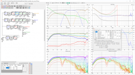
In the meanwhile, I cooked up a quick 3 way with the Satori woofers and SIca coax. Here is it.


I will do the circular baffle-based diffraction compensation in VituixCAD
I will study the aspects you suggested.
In the meanwhile, I cooked up a quick 3 way with the Satori woofers and SIca coax. Here is it.
Because the size of the archived project file is greater than 19MB, I have uploaded it here:
https://drive.google.com/file/d/1iO_GRfg7R-YlqiOZfjBM2P770oU5ERrs/view?usp=sharing
Requesting @fluid ,@tmuikku and everyone interested to take a look when you have time.. 🙂
https://drive.google.com/file/d/1iO_GRfg7R-YlqiOZfjBM2P770oU5ERrs/view?usp=sharing
Requesting @fluid ,@tmuikku and everyone interested to take a look when you have time.. 🙂
Attaching just one more iteration of crossover.. 😀


Null test for phase matching at crossover with mid inverted (just for fun 😀)

Null test for phase matching at crossover with mid inverted (just for fun 😀)
Last edited:
Band pass/CD horn EQ filter or DSP.I don't know what to do with that hump in the 10kHz - 20kHz region.
That's a pickle.
Sans KEF and Genelec, almost every coax has that funky top octave. And you can't EQ it out because it what is a dip on axis becomes a peak off axis, and vice versa. And there isn't a whole lot going on in music in that top octave, neither are our ears particular good in that top octave to guide us. Also depending on the room/humidity there's a whole lot of air damping going on.
I would leave it alone. If this was a commercial design you might have to EQ it out otherwise people might complain about it- It probably looks worse than is sounds.
Nice measurements & simulations! I've linked them from the end of my OB thread as a reference for anyone who might pick the Sica coax. Your results mostly match what I see and you've done a better job of the spin measurements. I'm extremely happy with this well-behaved little coax and don't expect to replace it any time soon as it sounds great with all the musical styles to which I listen.In the meanwhile, I cooked up a quick 3 way with the Satori woofers and SIca coax. Here is it.
Ken
edit: typo
Yeah that pod is very cool!
Wish I could do something like that with aluminium or one of those synthetic stones…
Wish I could do something like that with aluminium or one of those synthetic stones…
Yours is a great thread with participation from some great people.. 🙂Nice measurements & simulations! I've linked them from the end of my OB thread as a reference for anyone who might pick the Sica coax. Your results mostly match what I see and you've done a better job of the spin measurements. I'm extremely happy with this well-behaved little coax and don't expect to replace it any time soon as it sounds great with all the musical styles to which I listen.
Ken
edit: typo
I will read it completely and understand your design philosophy and experiences
You could 3D print a pod in SLS nylon if you like.. 🙂Yeah that pod is very cool!
Wish I could do something like that with aluminium or one of those synthetic stones…
It seems to be a good material. Now companies like this are making pods like these in SLS nylon in their commercial products:
https://www.node-audio.com/hylixa/
Thanks for posting your measurements. I'm having fun with them. I have been aware of the potential of the sica coax for some time and wanted to do something with it. I went so far as to buy a sample but its still in the box it came in. Your measurements will give my prior sims a dose of reality.
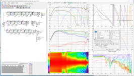
The first thing I did was add PEQs to treat that peak at ~12 Khz. The first attached file is your design with 2 PEQs added on the tweeter. The first peq attenuates the peak; the 2nd is a shelf filter that converts the flat PIR to downward sloping. This raised the predicted preference rating from 8.9 to 9.3. The predicted preference rating improvement is no substitute for a listening test but its an indication these changes might help. This is with H ref angle of 10 degrees.
I next noticed how narrow your vertical directivity is in the crossover region and how high you let the woofers play. That shouldn't be necessary as others have found the Sica Coax plays down to 100 Hz by itself quite well. To see what could be done about the narrowness at XO, I converted to a FIR XO. My process is to use Vituix's mirror function to flatten the driver response, add low pass or high pass filters for target XO and then go back and add IIR PEQs to smooth the PIR and power response. Some overlap between the woofer's and the Sica mids helped with that. My results are in the second attached file. Now going 20 degress off axis drops less than 2 db.
Attachments
Last edited:
I was wondeting about the very narrow vertical dispersion too. Xo around 2-300Hz...
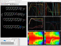
You can have way better vertical dispersion and flatter DI by converting from 3 way to 3.5 way and lowering the crossover between the woofers and the coax to about 400 hz. Shallower slopes help too.
Note there is a bump in PIR at 1-2 kHz region; it could be remediedd by another bandpass, but the on-oxis linearity will suffer somewhat. Ultimately this is the voicing decision which should be made according to direct/diffuse field ratio, listening distance and personal preference.
Note there is a bump in PIR at 1-2 kHz region; it could be remediedd by another bandpass, but the on-oxis linearity will suffer somewhat. Ultimately this is the voicing decision which should be made according to direct/diffuse field ratio, listening distance and personal preference.
Attachments

Last edited:
Thanks a lot 🙂Here is zip of my project directory, less the measurements, with 3 version of the design it: the original with two PEQs added, a FIR version matching the original driver placement, and a wCOAXw version.
Took me a while but I like this, diffraction hump around 500Hz and slightly higher group delay between 300Hz and 100Hz are the things that stick out to try and tweak. You can add 10 to 20us of delay on the mid to get a slightly tighter phase match at crossover but then the EQ needs tweaking as I made it without.
Attachments
- Home
- Loudspeakers
- Multi-Way
- A 3 way design study