So i designed a new enclosure for the coaxial drivers 😀
Using spline and rotate tools in fusion360, i created a teardropish shape as below. Depth of enclosure = 27cm, Maximum diameter = 22cm
The area where the driver is mounted follows the slant of the driver frame. The frame slants down by about 4 degrees.

Next I tried to 3D print a prototype in 3 parts. Overall enclosure is formed by 3 threaded sections.. The first part is printed

Here is the driver mounted in above part 😀

Right now, it is missing a gasket to be applied between the driver frame and enclosure. Hence that current 2mm looking recess of the driver when it is mounted..
I forgot to create the screw fixing holes in the enclosure before printing though.. 😀
Anyway.. onto printing the next part..
Using spline and rotate tools in fusion360, i created a teardropish shape as below. Depth of enclosure = 27cm, Maximum diameter = 22cm
The area where the driver is mounted follows the slant of the driver frame. The frame slants down by about 4 degrees.
Next I tried to 3D print a prototype in 3 parts. Overall enclosure is formed by 3 threaded sections.. The first part is printed
Here is the driver mounted in above part 😀
Right now, it is missing a gasket to be applied between the driver frame and enclosure. Hence that current 2mm looking recess of the driver when it is mounted..
I forgot to create the screw fixing holes in the enclosure before printing though.. 😀
Anyway.. onto printing the next part..

Just couldn't leave out linking this video here.. 😀
I have always wondered how the abrupt transition in directivity especially around the crossover point sounds like (in a speaker in which the transition is not taken care of properly like in typical two way speaker, where there woofer starts to beam and suddenly the tweeter which is radiating wide is brought in
Finally got to hear some clues about the perceptible effects of this phenomenon in this video where Geoff Martin speaks about it (after about 11 minutes):
Hi,
'Waistbending' ( as described by E.Geddes into his whitepaper / wide- narrow) i experience differently as explained in the video: for myself it change the ratio of direct/reverbered sound on a given bandwidth.
I've chased this effect for some years on my mains 3way ( they have ( had) it around 800hz). When you listen on axis ( which is how i use them) it's not really an issue but the info 'send' by the room are misleading when working on them to me because it kind of 'miss' this range ( 400/800hz is subdued).
If i only listened to them i could had probably not been bothered this much by it but once you have a second different pair of loudspeaker to compare and the 'non treated' material as reference then it is more obvious ( and not only to me as once pointed to other engineer and musicians, they usually recognize it).
I've not feeled the difference of depth he talk about in the video but maybe it's because i'm used to play with reverbs and identify the ratio of direct/ reverberant field minute?
Maybe for someone not used to this it could be interpreted as explained in the video?
Thank you Krivium. Your answer/experience widens my knowledge about this effect and regarding what to look for in future. 🙂I've not feeled the difference of depth he talk about in the video but maybe it's because i'm used to play with reverbs and identify the ratio of direct/ reverberant field minute?
Maybe for someone not used to this it could be interpreted as explained in the video?
I myself have not specifically listened to any of these effects because I maybe lacking critical listening skills..
I probably only detect something is wrong when something is really off. 😀
But I have been very curious about the "waistbanding" effect seeing it vituixcad plots and why people say it is good to have smooth directivity transitions at crossover.
Over here, people on local forums just say that I am too much into academic things and not focusing on audible impact of different design decisions.
Well now I have something to look forward to while listening for issues.. 😀
Thanks
Vineeth
I myself have not specifically listened to any of these effects because I maybe lacking critical listening skills..
I probably only detect something is wrong when something is really off. 😀
I don't think 'critical listening skills' are innate. Like many things, these are acquired by experience imho.
But I have been very curious about the "waistbanding" effect seeing it vituixcad plots and why people say it is good to have smooth directivity transitions at crossover.
Not only in the crossover bandpass: overall smooth directivity is key in my view.
ATC is a good example ( despite at the other end of what i like regarding the kind of directivity i prefer), Genelec,....
Over here, people on local forums just say that I am too much into academic things and not focusing on audible impact of different design decisions.
Well now I have something to look forward to while listening for issues.. 😀
Yeah, people always know what YOU should do! 😏
What do they think have an audible impact, i'm curious?
Vineeth i think your approach ( trying different 'acoustic design' and understanding how they behave/ their compromise) is the way to gain knowledge on what does mater to YOU in a design.
Critical listening is acquired, for sure.
In nursing, or medical school, when you first put on a stethoscope and listen to a patient's heart, or lungs, you have no idea what you are listening to. There are just sounds, and they all just sounds wildly different, (or wildly the same)
But you can't discern the difference.
It takes years of practice to figure out what you're hearing, how to differentiate what you're hearing and what it all means.
It's the same in the studio.
It's the same in the home.
Be careful what you wish for Vineeth. When I hear the PA speaker at the kids school playing the school "bell" song to signify the start of class... _
"OMG can someone please upgrade that squawker!" 🤣 😱
In my country, the musical heritage is very rich, vast and diverse that it is almost impossible to even classify/list out everything. Hence the music/sound production part has advanced a lot beyond probably what i will ever know 🙂What do they think have an audible impact, i'm curious?
But where we are lacking is the designing equipment for sound reproduction in rooms part. To the best of my knowledge, measurements-based speaker DIY in my country has not advanced much. Most people who are into it only take/are satisfied with impedance sweeps and just on axis measurements for crossover design. That number itself is less. Many are happy with traced curves from factory datasheets. Even companies who have become very successful in selling a lot of speakers to the "audiophile" community in the past few years don't go beyond that.
Here, suddenly i come in and try to take polars and show it to people. Most believe that it is all just nice pictures generated by VituixCad and don't have much relevance to how the speaker "sounds". Diffraction and directivity control etc are considered "features that are more of academic interest" and don't have much to do with good sounding speakers. I agree these are not the only important features and probably there are other features that contribute more to the "goodness" of perceived sound. But just neglecting it wont cause things to go away, I guess.. 🙂
I should mention that there are a few people, which I can count on the fingers of my hand, who even though they are limited to the reduced set of measurements mentioned above, have gathered enough knowledge and critical listening skills to make good sounding speakers. Me being an idiot in that aspect need/can only proceed further in making speakers with an exhaustive collection of data to see and understand what is happening with the speaker. 😀
I should also mention that there are companies here who have invested a lot in R&D and make good looking and probably good measuring speakers like these:
https://sonodyne.com/category/residential/speakers/srp-200-series/srp-205
But the local "audiophile" community is not interested in all that. Many have enough money to burn that they will gladly buy the "high end" brands at exorbitant costs.. Many are interested in high end tube amplifiers and even how speaker cables make a "lot of difference". To them these aspects matter more than speakers itself.
Now I am rambling but such is ths state of affairs here.. 😀
Thanks a lot.. 🙂Vineeth i think your approach ( trying different 'acoustic design' and understanding how they behave/ their compromise) is the way to gain knowledge on what does mater to YOU in a design.
In percentage terms so is the state of affairs everywhere. You are on the right path, explore the options that make sound acoustic sense and find out what you like.Now I am rambling but such is ths state of affairs here.. 😀
Waistbanding as a term is mostly used to describe the effect that happens in an asymmetric horn/waveguide where the vertical and horizontal patterns aren't the same, usually the vertical widens earlier because it's dimension is smaller and this causes the "pinch" or waistband.Maybe for someone not used to this it could be interpreted as explained in the video?
The same mechanism is at play in what Krivium describes, the polar patterns in the drivers don't match at crossover and create a discontinuity. It's rare for designers to choose to confine that to a small frequency band with steeper crossovers and make a pinch rather than spread it wider with lower slope crossovers.
I could image a confined frequency area having a more obvious effect of pulling an instrument towards the listener if the direct response is strong but the off axis cancelled. Over a wider range I find that harder to imagine.
I wonder sometimes if the interviewees would make less vague statements if they were talking to someone who actually understood what they were saying.
Not just your country brother.
In most places of the world, measurements is gobbledygook to lay people, and frowned on by most audiophiles- “just use your ears”
There is not yet a good metric on which to judge “quality”,
most people still buy with their eyes and the price tag.
At the entry level/budget end, whether it
“Goes loud!” or “Has lots of bass!” (100Hz)
The music and recording professionals are better and less tweakazoid… but not always.
Last edited:
Thanks everyone for the encouragement.. 🙂
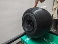
So I printed out the prototype enclosure for the coaxial driver 😀
Here it is:


Those gaps between sections is a combination of little bit of warping in the individual prints and me being an idiot an tearing out part of the threading in one of the pieces thinking it is support. 😀
Anyway, it all seems to fit together really well except for those small gaps. Since this is just a prototype, I am thinking of filling it up/covering it up with some of adhesive tape after all the other works are done.
Next I am thinking of doing a little bit of sanding in places it is needed, cover the insides with aluminium butyl sheets and put some melamine foam at the back and inside the enclosure a little away from the drivers. I also need to carefully drill holes for driver attachment and at the moment, i dont know how the plastic is going to take it, but i will try.. will also add a 2-3mm thick rubber gasket between driver and enclosure.. 😀
So I printed out the prototype enclosure for the coaxial driver 😀
Here it is:
Those gaps between sections is a combination of little bit of warping in the individual prints and me being an idiot an tearing out part of the threading in one of the pieces thinking it is support. 😀
Anyway, it all seems to fit together really well except for those small gaps. Since this is just a prototype, I am thinking of filling it up/covering it up with some of adhesive tape after all the other works are done.
Next I am thinking of doing a little bit of sanding in places it is needed, cover the insides with aluminium butyl sheets and put some melamine foam at the back and inside the enclosure a little away from the drivers. I also need to carefully drill holes for driver attachment and at the moment, i dont know how the plastic is going to take it, but i will try.. will also add a 2-3mm thick rubber gasket between driver and enclosure.. 😀
Attachments
In my country, the musical heritage is very rich, vast and diverse that it is almost impossible to even classify/list out everything. Hence the music/sound production part has advanced a lot beyond probably what i will ever know 🙂
Sure, civilisation with long history, vast territory and this much people can only exibit infinite variation of cultural expression.
From your 'classical music' to bollywood and more.
Me being an idiot in that aspect need/can only proceed further in making speakers with an exhaustive collection of data to see and understand what is happening with the speaker. 😀
An idiot?! How could it be as you have rational scientific approach?
I mean you start collecting data, in no time you'll have way enough to make link to what is important to you.
The local "audiophile" community is not interested in all that. Many have enough money to burn that they will gladly buy the "high end" brands at exorbitant costs.. Many are interested in high end tube amplifiers and even how speaker cables make a "lot of difference". To them these aspects matter more than speakers itself.
Ah ok. So self defined 'Audiophile' often use their hobby as a marker of ( social) class.
Nothing to learn there except arrogance ime.
Scientific approach will certainly bring more rewards and knowledge. Better sound too once you identify what please you.
how much does something like this cost In materials I'd love to be able to make something like this its very coolThanks everyone for the encouragement.. 🙂
So I printed out the prototype enclosure for the coaxial driver 😀
Here it is:
View attachment 1082838
View attachment 1082839
View attachment 1082840
View attachment 1082843
Those gaps between sections is a combination of little bit of warping in the individual prints and me being an idiot an tearing out part of the threading in one of the pieces thinking it is support. 😀
Anyway, it all seems to fit together really well except for those small gaps. Since this is just a prototype, I am thinking of filling it up/covering it up with some of adhesive tape after all the other works are done.
Next I am thinking of doing a little bit of sanding in places it is needed, cover the insides with aluminium butyl sheets and put some melamine foam at the back and inside the enclosure a little away from the drivers. I also need to carefully drill holes for driver attachment and at the moment, i dont know how the plastic is going to take it, but i will try.. will also add a 2-3mm thick rubber gasket between driver and enclosure.. 😀
Material costs involved in printing this enclosure is very low.. 🙂 I printed this using PLA+ filament on my Creality Ender 5 pro 3D printer. The filament cost for 2 x 1kg filaments is Rs 2000/- in india.. equivalent to approx 25 US dollars. This is more than enough to print 2 such enclosureshow much does something like this cost In materials I'd love to be able to make something like this its very cool
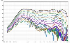
Orb under measurements 😀


All measurements are gated at 4.5ms
Woofer polar upto 180 degrees

Tweeter polars upto 180 degrees

Driver response in VituixCAD with basic filters
 Drivers and crossover making in VituixCAD
 I really need some help with this crossover on this one. I dont know hoe the sound balancing should be done here..
I will post the VituixCad project here tomorrow. 😀
All measurements are gated at 4.5ms
Woofer polar upto 180 degrees
Tweeter polars upto 180 degrees
Driver response in VituixCAD with basic filters
I will post the VituixCad project here tomorrow. 😀
Attachments

Last edited:
Consider baffle step compensation.
There’s are 3 ways to do approximate this-
Take a outdoor ground plane measurement at @2m
OR:
Or use TS parameters to model the in-box anechoic response in Enclosure, then subtract the diffraction response using Diffraction
OR:
Eyeball it and add a shelf filter

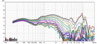
With a 4.5ms gate your frequency resolution is about 222Hz, which between there’s a lot of smoothing going on under 1KHz.
Here's an example of effects of using gate lengths of 5ms, 6ms and 10ms, on measured low end response:

There’s are 3 ways to do approximate this-
Take a outdoor ground plane measurement at @2m
OR:
Or use TS parameters to model the in-box anechoic response in Enclosure, then subtract the diffraction response using Diffraction
OR:
Eyeball it and add a shelf filter
With a 4.5ms gate your frequency resolution is about 222Hz, which between there’s a lot of smoothing going on under 1KHz.
Here's an example of effects of using gate lengths of 5ms, 6ms and 10ms, on measured low end response:
Last edited:
My best effort so far for the mid-tweeter crossover

Crossover

I don't know what to do with that hump in the 10kHz - 20kHz region.
Also, I don't know what is the power response target I should be aiming for with these drivers.
Ultimately, I want to use the Satori woofer box in a configuration like this (please don't mind that green rubber ring or the cellophane tape at the joints 😀 ).

I am trying to resolve issues with archiving VituixCAD project and upload a copy here including all drivers next
Crossover
I don't know what to do with that hump in the 10kHz - 20kHz region.
Also, I don't know what is the power response target I should be aiming for with these drivers.
Ultimately, I want to use the Satori woofer box in a configuration like this (please don't mind that green rubber ring or the cellophane tape at the joints 😀 ).
I am trying to resolve issues with archiving VituixCAD project and upload a copy here including all drivers next
- Home
- Loudspeakers
- Multi-Way
- A 3 way design study