Ok sir I will try to search 1.5watts
But sir substitute of ic irs2117 and diode bav21
Thanking u yours
But sir substitute of ic irs2117 and diode bav21
Thanking u yours
vertex 2500 amp
Did any one try vertex 2500 amp . Pls update hiw is it. Is that amp stable and reliable for outdoor shows. I know mr.jay has made it, but did not given any further update about the amp , but he has given many good coments of h900 .
Pls if anyone built vertex and use sucessesfully pls update
Did any one try vertex 2500 amp . Pls update hiw is it. Is that amp stable and reliable for outdoor shows. I know mr.jay has made it, but did not given any further update about the amp , but he has given many good coments of h900 .
Pls if anyone built vertex and use sucessesfully pls update
Ok, heres the thing , i've disconnected one of the boards and powered just one and it powered up the relay kicked in and everything was fine , so I guess the fault lies still in some short or else in the unconnected circuit.I will try to sort that out.
as for the transformer I guess there are two ways to connect it.One was working like you showed thimios , but the other way I did also worked last night. I did it like this, check the attached picture.
as for the transformer I guess there are two ways to connect it.One was working like you showed thimios , but the other way I did also worked last night. I did it like this, check the attached picture.
Attachments
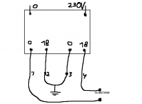
post3440 is almost correct.
The two middle pins of the secondary get connected to form a Centre Tap.
The two outer pins are the AC supply to the bridge rectifier.
The bridge recifier supplies +ve and -ve to the series pair of smoothing caps. The junction of the smoothing caps is connected to the Centre Tap.
The centre of the smoothing capacitors is your PSU Zero Volts.
The centre of the secondary windings is your Centre Tap.
Neither of these is ground.
Dear sir,
Thanks but 1.3 watt ,can I use 1watt zener in place of 1.3w.one more question is that what are substitute of bav21,and ic 2117 b'cause these are not available in my area thanks with regard
Theoriticaly no ! BAV21 is a Diode not a Zener
Folks, can I ask for some advice.I've made one of the two protection circuit boards work and it works fine.
The other one is a pain in the as*.
When I connect just the other one the output voltage from the transformer drops to 1.5 volts.
Yes at first this simple circuit had my faults from a badly made pcb it had some shorts in the shape of small tiny copper bits from trace to trace , since the board is small it didn't take me long to go over it and clean every trace inbetween, so now that the traces are cleared and the tester shows no more shorts the same problem still applies , as the traffo goes on the voltage is only 1.5 so there is excess current draw.But the problem is I can't seem to find where , I measured the rectifier diodes their ok, I've take out the IC and the same thing still goes on, I now took out both 7815 and 7915 voltage regulators effectively disabling the whole +-15v chain and the same happens , then took out the 7812 regulator for the fan and still the same.
the only thing left now in is the 2n5401 transistor in series with the relay coil but even if the transistor failed open the relay coil is still made to be driven constantly and represents no such load as to collapse the voltage of my transformer.
I feel like i'm lost in 3 trees , any more ideas what takes up so much current ?
Attachments
The output from the mains transformer dops to 1.5Vac !
That indicates a massive overload condition.
Fit your Mains Bulb Tester. Then try again.
That indicates a massive overload condition.
Fit your Mains Bulb Tester. Then try again.
thank you Andrew and thimios for reaching out , I finally found the problem , it's a rather funny one there was still some mini tiny trace left short circuiting two traces , well one pcb turned out good but the other i had problems with the toner wasn't sticking so good so i did some manual marker adjustments and they spoiled my pcb so i had to go through all this manual checking for short circuits but not it works finally , so i'll see how it goes further when i will now assemble this into the amp.
Also does anyone know what's the voltage at which the protection circuit starts to switch off the output when it senses DC in the output ?
I've added the extra two channels , now I have 4 channels each 2 for their own stereo protection circuit , the first two work fine , the second two , one is ok the other one shows about 5.8 volts with minus sign in the output , but the relay kicks in nevertheless and so i can measure those DC at the output , well i have to first understand why i have dc at the output on that channel and second why the protection circuit allows the relay to work even though there is DC.
both channels are b500 without the mosfet rail drivers.
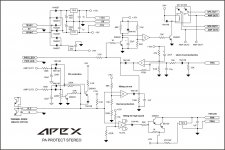
The Apex DC detect shown in post3448 uses a bridge rectifier to convert the AC signal from the amplifier output to DC. It also has a 150k in the RC filter and 220k in the tail of the rectifier. That will result is a fairly high voltage required before the trigger sets.
Test your DC detect and find out what DC voltage that detect circuit needs to trigger the relay. See if both behave similarly.
Test your DC detect and find out what DC voltage that detect circuit needs to trigger the relay. See if both behave similarly.
Ok sir I will try to search 1.5watts
But sir substitute of ic irs2117 and diode bav21
Thanking u yours
i have ir 2117 if you want tell me 100 rs each. i will courier from ludhiana if you want.best of luck
Nice work.
Thank you sir apex,this is my first time to build power amplifier,and im so lucky its work fine,clear sound and powerful,thanks for sharing your designed sir
Apex Audio PA Prot Cicuit
dear Apec Audio Sir,
Can I use the PA Prot for BA2000 without any modofication. I can specially thinking about the short circut part of pa part. is there any modofication to be done according to BA2000 circuit ?
Nice work.
dear Apec Audio Sir,
Can I use the PA Prot for BA2000 without any modofication. I can specially thinking about the short circut part of pa part. is there any modofication to be done according to BA2000 circuit ?
- Home
- Amplifiers
- Solid State
- 900W H-class PA Amp with Limiter