hellow sir,pls go to the trhead #197 page 20,h900v2 pcb mr apex post,thats the pcb i use in my h900 project idont know if corrected or not,because for my h900 works fineWhere is ammended class h 900 pcb
I mean corrected pcb
Thanks

Please upload the pcb (design) original.
also raises the pcb (design) original. the previous message.
pcb please...
more detail
Hi sandeep,
can you provide more detail for this HD3600 amp pcb, schematic or more..
thanks
Anyone tryed this HD3600?
Hi sandeep,
can you provide more detail for this HD3600 amp pcb, schematic or more..
thanks
hi all my layout of apex h with transitor drive please check and add comments or compliments
Hi stewin
please send pcb and silkscreen file on my email
raval.himanshu@rediffmail.com
thanks
hi himan i have changed to smd , i have started on smd version . i have not finished yet . i am concentrating on class d bridging on +/-85vlts
Hi folks , could anyone of you help me out , I built the stereo protection board for my h900 and haven't soldered in two parts , one is the protection LED and the other is the bd241c transistor used as a heat sensing part.
could this cause my board to not work ?
I myself tend to think that according to the schematic the transistor needs to be in in order for the IC to power up the relay since now it's getting 0 volts on its coil.
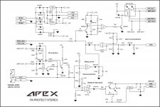
What do you think? I will add the schematic so that you don't have to search it.
could this cause my board to not work ?
I myself tend to think that according to the schematic the transistor needs to be in in order for the IC to power up the relay since now it's getting 0 volts on its coil.
What do you think? I will add the schematic so that you don't have to search it.
Attachments


Attention, diode in red circle must be reversed.Hi folks , could anyone of you help me out , I built the stereo protection board for my h900 and haven't soldered in two parts , one is the protection LED and the other is the bd241c transistor used as a heat sensing part.
could this cause my board to not work ?
I myself tend to think that according to the schematic the transistor needs to be in in order for the IC to power up the relay since now it's getting 0 volts on its coil.
What do you think? I will add the schematic so that you don't have to search it.
Attachments
Last edited:
apex h900 current limiter
Hi dear Apexaudio Sir,
can I use the current limiter part of vertex amp for H900. Apex h900 amp doesn't have a current limiter but only the bias multiplier.
Or could you please provide us the correct suitable current limiter for H900 .
Apex Sir OR any other Expert please help .......
Hi dear Apexaudio Sir,
can I use the current limiter part of vertex amp for H900. Apex h900 amp doesn't have a current limiter but only the bias multiplier.
Or could you please provide us the correct suitable current limiter for H900 .
Apex Sir OR any other Expert please help .......
Attachments
Yes, You can use V/I limiter in the H900, or in Vertex. It will gives You better safety in case of overload or short circuit.
You have to calculate the resistor values for the maximum allowed current.
Sajti
You have to calculate the resistor values for the maximum allowed current.
Sajti
Hi dear Apexaudio Sir,
can I use the current limiter part of vertex amp for H900. Apex h900 amp doesn't have a current limiter but only the bias multiplier.
Or could you please provide us the correct suitable current limiter for H900 .
Apex Sir OR any other Expert please help .......
If you add protection to the output stage, you risk blowing up the previous stage.Yes, You can use V/I limiter in the H900, or in Vertex. It will gives You better safety in case of overload or short circuit.
You have to calculate the resistor values for the maximum allowed current.
Sajti
Note that the sch shows 47r just before the diode+transistor shorting to the output rail.
This 47r becomes the "load" for the previous stage.
The previous stage must be able to drive this load, or protected to survive this load.
If you add protection to the output stage, you risk blowing up the previous stage.
Note that the sch shows 47r just before the diode+transistor shorting to the output rail.
This 47r becomes the "load" for the previous stage.
The previous stage must be able to drive this load, or protected to survive this load.
It's not true! Calculate the 47ohm series resistor+the 68ohm resistor in the emitter of the VAS stage! And the VAS based on MJ15034/35, which are 4A transistors. They should easy handle the current.
Sajti
Read what I posted and read what you replied with.
The previous stage must be able to drive this load,
Read what I posted and read what you replied with.
I did it. Calculate only with the 47ohm is wrong. The 68ohm will limit the maximum current too. I did simulation with V/I limiters.
Sajti
so could you please tell whether the transistor BD241c is crucial to the working of the apex protection circuit ?
also what are the analogues to the bd241c ?
it's just that i already have a thermoswitch safety for the output heatsinks maybe I can bypass the bd241c in the protection board for it to work and provide me the other safety features like DC protection and overload etc?
thank you.
also what are the analogues to the bd241c ?
it's just that i already have a thermoswitch safety for the output heatsinks maybe I can bypass the bd241c in the protection board for it to work and provide me the other safety features like DC protection and overload etc?
thank you.
Last edited:
I get from your answer Ian that I can indeed replace them with the 243c version since in both your mentioned TIP case and the BD241/243c case it's mainly just higher collector current that differs them.
?
?
Ok folks , I ran into this problem , I got a 6VA rated little transformer with two secondaries each 3VA and 18volts, I wanted to power my apex protection circuit from it.
Now maybe it is worth noting that i have two stereo protection circuits powered in parallel , as I have 4 channels one circuit for each two channels.
now when i run the transformer unloaded it shows about 20 volts out measuring from center to each side, as soon as I connect the wires it shows 0.5 volts on each side , the transformer inner wire seems very very think when i look at it and it seems it's physically unable to deliver the load.
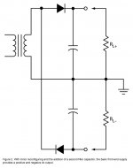
I have a larger and thicker wire secondary , transformer , but it has only one secondary output winding,
can I use it somehow to make a floating ground and have it as bipolar psu for this protection circuit ?
I have attached the schematic I could use to make it bipolar.
what do you think?
Now maybe it is worth noting that i have two stereo protection circuits powered in parallel , as I have 4 channels one circuit for each two channels.
now when i run the transformer unloaded it shows about 20 volts out measuring from center to each side, as soon as I connect the wires it shows 0.5 volts on each side , the transformer inner wire seems very very think when i look at it and it seems it's physically unable to deliver the load.
I have a larger and thicker wire secondary , transformer , but it has only one secondary output winding,
can I use it somehow to make a floating ground and have it as bipolar psu for this protection circuit ?
I have attached the schematic I could use to make it bipolar.
what do you think?
Attachments
- Home
- Amplifiers
- Solid State
- 900W H-class PA Amp with Limiter