Yes, You can use V/I limiter in the H900, or in Vertex. It will gives You better safety in case of overload or short circuit.
You have to calculate the resistor values for the maximum allowed current.
Sajti
Hi Sajti, thanks for the reply. but what I really need to know is , Is h900 tef with 8 pairs and having 30 ohms to mid point and 150 ohms to mid point from 5200 and 1943 ( tripple emiter ) and with nsl32 SIGNAL LIMITER,
will H900 amp works with out any heating issue.
According to my knowledge when the transistors work it get hot so due to that it will take more current, again due to more current it takes, it gets more heat, this will continue until output stage transistors die.
So to prevent this lot of power amps I have seen CURRENT LIMITER for output stage ,which is there on apex vertex 2500 amp. But not in H900.
So is ONLY the SIGNAL LIMITER ( nsl32 ) enought for h900 to run over night at outdoor shows without any thermal issues ?
I guess VI limiter is there for SHORT CIRCUIT protection. but CURRENT LIMITER of OUT PUT STAGE is different from the VI Limiter according to my knowledge . lot of power amps which doesn't have short circuit protection have current limiter like in VERTEX amp. Crest audio, zeck ca1600, only FET amps I have not seen current limiter as fet works like a iron. ( when work it get hot up to some temperature and stay on that point continuously. but transistors get heat and current until it dies, if theres no control of the current.
THESE EXPLANATION IS ACCORDING TO MY KNOWLEDGE , IF I AM WRONG , I WOULD LOVE TO LEARN THE CORRECT PROCEDURE.
Could you please tell me VI limiter and current Limiter of OUTPUT stage SAME ?
I really don't undestand
Last edited:
6VA 18+18Vac has a maximum continuous AC rating of 166mAacOk folks , I ran into this problem , I got a 6VA rated little transformer with two secondaries each 3VA and 18volts, I wanted to power my apex protection circuit from it.
Now maybe it is worth noting that i have two stereo protection circuits powered in parallel , as I have 4 channels one circuit for each two channels.
now when i run the transformer unloaded it shows about 20 volts out measuring from center to each side, as soon as I connect the wires it shows 0.5 volts on each side , the transformer inner wire seems very very think when i look at it and it seems it's physically unable to deliver the load.
I have a larger and thicker wire secondary , transformer , but it has only one secondary output winding,
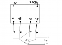
can I use it somehow to make a floating ground and have it as bipolar psu for this protection circuit ?
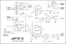
I have attached the schematic I could use to make it bipolar.
what do you think?
the maximum continuous DC current is ~ 90mAdc.
To allow the transformer to run cooler aim for ~ half that maximum, i.e. <50mAdc continuous.
Your protection circuit should operate with a lot less than 25mA per board.
What have you done wrong?
I presume you have 18+18Vac because you have 24Vdc relay coils.
Is that correct?
BTW,
I have a selection of 3VA, 5VA and 6VA EI transformers rated for 6+6Vac, 9+9Vac and 12+12Vac to power auxiliary circuits. I don't have any problem with collasping supply rail voltage/s.
I recently experimented with a 6VA, 12+12Vac to power a B.Putzeys' bal vol pot. It ran @ ~80% of it's maximum rating. As expected it ran very warm, too hot to hold my finger on the exposed core. I decided this was too hot for me. But the supply rail voltages did not collapse. In fact they were too high and I added 200r to each secondary to reduce the peak current and reduce the voltage fed to the 12V regulators. Even with the 200r+200r of added resistance the transformer still ran too hot.
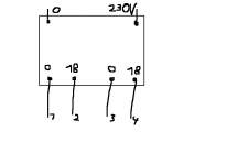
I have a transformer with to separate secondary windings , each rated 3VA, each 18 volts.
I connected them like this, one windings end is tied with the next ones start , not sure whether that's the way inside the traffo but since i cant see inside just at the outside terminals this is the way i connected it.
so now as I measure from the center i get about 20 volts each way.so it's about 20-0-20, as soon as I connect the load i get about 0.5 v each direction.
If the schematic is right and doesn't have one of those special mistakes put in so that the dumb copycats can't copy it then there's something wrong with my soldring maybe , I am checking this now.
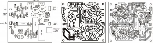
Have you seen the post #3409?I really don't know , I've built everything according to this schematic and layout picture
yes thimios , thank you , I reversed the diode , but that surely isn't the cause of my current problem.but anyway it was a mistake either accidental or deliberate on the layout picture.
This ia a working circuit,can you please explain what is your problem?yes thimios , thank you , I reversed the diode , but that surely isn't the cause of my current problem.but anyway it was a mistake either accidental or deliberate on the layout picture.
yes , the transformer sags dead when i connect the circuit , before connection it outputs about 20-0-20 volts but when i connect it it goes to 0.5 volts.
its a small 6VA transformer.
the circuit itsel appears to be ok, measured both circuit input at the diode rectifier and they show the correct values no short circuits.
sadly i dont have a stronger transformer to test just for curiosity.
its a small 6VA transformer.
the circuit itsel appears to be ok, measured both circuit input at the diode rectifier and they show the correct values no short circuits.
sadly i dont have a stronger transformer to test just for curiosity.
Does the bulb of the Mains Bulb Tester light up?Did you see the bulb of the Mains Bulb Tester light up?
Fan polarity is wrong ,did you correct it?yes , the transformer sags dead when i connect the circuit , before connection it outputs about 20-0-20 volts but when i connect it it goes to 0.5 volts.
its a small 6VA transformer.
the circuit itsel appears to be ok, measured both circuit input at the diode rectifier and they show the correct values no short circuits.
sadly i dont have a stronger transformer to test just for curiosity.
Now i see, your schematic is ok.
Did you test the circuit with a fan attached.
Is your transformer suitable (enough current) for fan operation?
Last edited:
yes I just did a test and a 25w bulb glows mildly but beautifully when connected in series with the primary of the transformer , the secondary shows 0.4 volts of output.
I have no fan attached , I made my box and heatsinks such that no fan is required.
I have no big load attached to the circuit just the protection circuit itself.
I have no fan attached , I made my box and heatsinks such that no fan is required.
I have no big load attached to the circuit just the protection circuit itself.
apex h900 current limiter
Please can any expert advise me ?
Hi Sajti, thanks for the reply. but what I really need to know is , Is h900 tef with 8 pairs and having 30 ohms to mid point and 150 ohms to mid point from 5200 and 1943 ( tripple emiter ) and with nsl32 SIGNAL LIMITER,
will H900 amp works with out any heating issue.
According to my knowledge when the transistors work it get hot so due to that it will take more current, again due to more current it takes, it gets more heat, this will continue until output stage transistors die.
So to prevent this lot of power amps I have seen CURRENT LIMITER for output stage ,which is there on apex vertex 2500 amp. But not in H900.
So is ONLY the SIGNAL LIMITER ( nsl32 ) enought for h900 to run over night at outdoor shows without any thermal issues ?
I guess VI limiter is there for SHORT CIRCUIT protection. but CURRENT LIMITER of OUT PUT STAGE is different from the VI Limiter according to my knowledge . lot of power amps which doesn't have short circuit protection have current limiter like in VERTEX amp. Crest audio, zeck ca1600, only FET amps I have not seen current limiter as fet works like a iron. ( when work it get hot up to some temperature and stay on that point continuously. but transistors get heat and current until it dies, if theres no control of the current.
THESE EXPLANATION IS ACCORDING TO MY KNOWLEDGE , IF I AM WRONG , I WOULD LOVE TO LEARN THE CORRECT PROCEDURE.
Could you please tell me VI limiter and current Limiter of OUTPUT stage SAME ?
I really don't undestand
Please can any expert advise me ?
Then check your circuit for wrong polarity electrolytic capacitors or regulators,diodes or short circuit by solder points.yes I just did a test and a 25w bulb glows mildly but beautifully when connected in series with the primary of the transformer , the secondary shows 0.4 volts of output.
I have no fan attached , I made my box and heatsinks such that no fan is required.
I have no big load attached to the circuit just the protection circuit itself.
Last edited:
That bulb filament lighting up tells you the circuit is drawing too much current.yes I just did a test and a 25w bulb glows mildly but beautifully when connected in series with the primary of the transformer , the secondary shows 0.4 volts of output.
I have no fan attached , I made my box and heatsinks such that no fan is required.
I have no big load attached to the circuit just the protection circuit itself.
Sort the wiring.
If necessary go back to just the transformer. test.
add on the bridge rectifier. test
add on the smoothing. test.
add on the second rectifier. test.
add on the second smoothing. test.
Once you have the correct voltages at the two sets of smoothing and the bulb is NOT glowing, then you can add on the protection circuit.
Last edited:
Ok, I measured the pcb and found out that one of the two pcb had many short circuit points were the traces were touching which was unseen by the naked eye but when upon closer inspection it resulted in such.sadly the pcb turned out kinda crappy and was messing with my head , now I sorted it out
just of curiosity , what the right way to connect the two secondary windings of the transformer to form a bipolar supply ?
I attached a ms paint picture of my transformer layout
just of curiosity , what the right way to connect the two secondary windings of the transformer to form a bipolar supply ?
I attached a ms paint picture of my transformer layout
Attachments
What is zf15 ; zy15 diodes
ZF15 = Zener 15V 0,5W
ZY15 = Zener 15V 1,3W
Ok, I measured the pcb and found out that one of the two pcb had many short circuit points were the traces were touching which was unseen by the naked eye but when upon closer inspection it resulted in such.sadly the pcb turned out kinda crappy and was messing with my head , now I sorted it out
just of curiosity , what the right way to connect the two secondary windings of the transformer to form a bipolar supply ?
I attached a ms paint picture of my transformer layout
Attachments
ZF15 = Zener 15V 0,5W
ZY15 = Zener 15V 1,3W
Dear sir,
Thanks but 1.3 watt ,can I use 1watt zener in place of 1.3w.one more question is that what are substitute of bav21,and ic 2117 b'cause these are not available in my area thanks with regard
- Home
- Amplifiers
- Solid State
- 900W H-class PA Amp with Limiter