apex
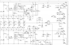
is there a better way of having the schematics?parts are not readable when maximize in this forum
can i have a clear copy?here is my e mail engel9mcnaly@yahoo.com
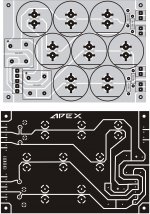
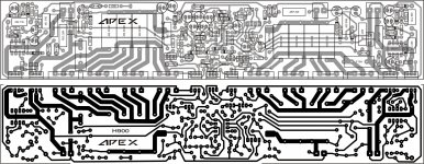
including schematics pcb pattern and p.s.u.
tnx.engel
is there a better way of having the schematics?parts are not readable when maximize in this forum
can i have a clear copy?here is my e mail engel9mcnaly@yahoo.com
including schematics pcb pattern and p.s.u.
tnx.engel
as i said before there is too much of interest in this kind of too much power class h
hoping to see the schema's and checking all available parts in our place
even so the replacements
hoping to see the schema's and checking all available parts in our place
even so the replacements
"Higly recomended German amplifier schematic" there is to much of interest, not for H-class amplifier, but there is masterpiece of advertising, ok that is kind of human nature.as i said before there is too much of interest in this kind of too much power class h
hoping to see the schema's and checking all available parts in our place
even so the replacements
"to me German is one of the best engineers in the world" but i really like the simplicity of your rail switching schemes
I'd love to see more threads like this. Nice way to use IR2117.
Mixing class H with "Vish" error correction (rush cascode) output stage could be interesting. Advantages include automatic biasing, no crossover distortion and probably less THD due to class H switching.
These are two unconventional output stages of special interest:
http://www.diyaudio.com/forums/solid-state/162759-class-b-revishited.html
http://www.diyaudio.com/forums/solid-state/154388-its-cheap-its-n-its-dirty-its-circlomos.html
(I'd like to see more threads like these too).
A few years ago I had a class H N-channel output stage with automatic biasing and error correction in mind, but I jumped directly into class D.
Last edited:
hi apexaudio
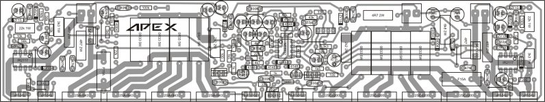
greetings trying to make your amp have almost made pcb pattern lots of
hard work you mentioned protection circuit has it a different pcb or can any other
dc protection circuit be used as i have some protection circuits ready
1 for commutatordiode can 2 byg 80 diodes be used in parallel
2 advise me output tranistors mjl 21194 mjl 21194 or 2sa5200 1943 wich combination shoud i use
3 power supply schematic would make things easier as i am making h class first time
4 should i use high speed bridges or normal bridges
5 any tips while making would be useful
thanks for your circuit and support
thanking you
andrew lebon
Hello apexaudio
To know more about the IR2117, I've download the spec-sheet, in this document the pin 3 are the ground, in your Apex H900 the pin 3 are named VSS, is it the same ground pin with VSS name ?
I presume that the 4R7 resistor and 47NF cap across the SFA1603 are to reduce the switching noise of that SFA1603 ?
Thank
Bye
Gaetan
Attachments
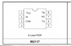
This is a floating high-side gate driver. It uses two supply voltages: Vcc to COM, and VB to VS. VB to VS voltage is usually generated through a bootstrap capacitor and diode. This capacitor is charged when the MOSFET is turned off and it keeps the floating part of the IC powered when it is turned on. Capacitor value determines the maximum time it can be kept turned on.
Certain rules have to be followed: The most important one: VS must not go below COM, altough negative transients are allowed with some restrictions. VS can temporarily go 5V below COM without problems. Additionally, VS can go up to (VB-VS) volts below COM but any change in input signal will be ignored during this time.
Certain rules have to be followed: The most important one: VS must not go below COM, altough negative transients are allowed with some restrictions. VS can temporarily go 5V below COM without problems. Additionally, VS can go up to (VB-VS) volts below COM but any change in input signal will be ignored during this time.
![P0947[01]_12-03-10.jpg](/community/data/attachments/142/142200-1688d92e9311f82ff2367be74fdee58f.jpg?hash=FojZLpMR-C)
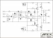
H900 VAS Part List:
R1-3k3
R2-10k
R3-33k
R4-43k
R5-47k
R6,R7,R8,R9,R13,R14-4k7
R10,R11,R19-22k
R12,R15,R16-1k
R17,R18-1k5
R20,R21-100R
R22-680R
R23-330R
R24,R25-2k2/2W
C1,C8,C9-22uF/25V
C2-33pF
C3,C4-2,2uF/63V
C5-470pF
C6,C7-47uF/25V
C10,C11,C12-100nF/63V
D1,D2,D3,D4,D5,D6-1N4148
Z1,Z2-ZY15V
Q1-2N5401
Q2-2N5551
Q3,Q5-MJE340
Q4-MJE350
IC1-NE5532
LDR-NSL32
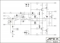
This circuit is for example, I will post limiter (LDR) driver circuit and protect circuit.Hi Apexaudio,
It seems LDR is incomplete as a function.
Clip Limiter
R26-6k8/2W, D7-1N4007, Z3-ZY15V
If amplifier output voltage is over 100Vp (+HV~115V DC) limiter will be active.
R26-6k8/2W, D7-1N4007, Z3-ZY15V
If amplifier output voltage is over 100Vp (+HV~115V DC) limiter will be active.
Attachments
Last edited:
- Home
- Amplifiers
- Solid State
- 900W H-class PA Amp with Limiter