hi apex sir,
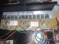
my h900 protection board is not working properly.
my protection light is not lighting when i power on,
i saw some power amps when the switch is on the protection light is lighting after one second the light is off.
is it working this way or no lighting on.
It is working this way.
hi apex sir,
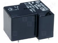
can i use this 30a 24vdc relay for h900 protect pcb.?
i know its not fitting to the protect pcb.
Yes there isn't shunt resistor in series with relay, any 24vdc relay can be use.
Dear Ravpreet
IR2117 Rs200 each
minimum order quantity - 10 nos.
courier charges Rs 100 extra
you can use UF4004 instead of BAV21
if you want receive private message, enable- receive private messages system
IR2117 Rs200 each
minimum order quantity - 10 nos.
courier charges Rs 100 extra
you can use UF4004 instead of BAV21
if you want receive private message, enable- receive private messages system
Dear Apex
I have lot of 12v 30amp relays, To use them in protect PCB, what changes should be apply.
I have lot of 12v 30amp relays, To use them in protect PCB, what changes should be apply.
Dear Apex
I have lot of 12v 30amp relays, To use them in protect PCB, what changes should be apply.
I suggest this protect with NE555 for 12V relays.
Attachments
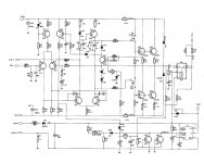
Thanks for circuitI suggest this protect with NE555 for 12V relays.
please post PCB Layout, if you have

hi apex sir,
pls can u share the protection pcb top and bottom in pdf format.
so i can edit to 30a relay.
thanks.
pls can u share the protection pcb top and bottom in pdf format.
so i can edit to 30a relay.
thanks.

hi chestap
greetings work in progress tell you result today
warm regards
andrew lebon
Is the layout can be weeks to appear, thanks
Nazir,
measure the coil resistance. Check that it pulls in with either polarity of supply. Some relays only pull in with one polarity.
Measure the switching terminals for zero volts. Normally Closed pair will read zero ohms. Normally Open pair will read open circuit.
Apply power to relay. The NO will now read zero ohms and the NC will read open circuit.
The common terminal is the one of each pair that is common to those zero ohm readings.
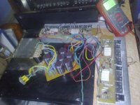
this is 600va transformer. after testing,two transformers will be used for 2 zone.sir ur transformer is very smal.....!!!!!
without load you have high voltage on output .
If offset is normal , install some speaker and test or take oscilloscope and see what happen when led is light ( whit 4 or 8 ohm resistor )
Regards !
If offset is normal , install some speaker and test or take oscilloscope and see what happen when led is light ( whit 4 or 8 ohm resistor )
Regards !
- Home
- Amplifiers
- Solid State
- 900W H-class PA Amp with Limiter