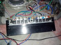
please post clear photos of your project.
Attachments
Last edited:
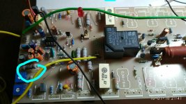
i only post for stewin so that he can examine things for his project.is this design fault or you did something wrong?Hi sir,rohin
this apex discrete stepper is not working properly,negative side suddenly increased rail
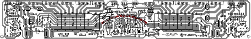
on which pcb file you made this ? please share that file so we can see if something wrong on pcb layout.
hi everyone can i use 7 pair output transistor with this ef version .if i use preset in place of r22 will it ok or i need to change r23 value too.thanks for your valuable comment.
Hi sir stewin, in your post #3597 can I put resistor in parallel with MUR810 (ex: 10K, 2watts) to serve as load resistance of IRF540 with respect to +MV? this will ensure that the voltage at +DMV will rise close to +HV when IRF540 switches ON. Without load resistance the voltage at +DMV will be undefined due to the collectors of C3856 acting as current sink and the IRF540 as current source in my opinion, am I correct?
hi guys,sir miles
just want to know if i can use the step drive schematics of vertex 3 tier using 0-42-94-142 dc split power supply from jbl mpx1200 transformer with 4 pairs of mjl21195/96 output devices?did someone here try 3 tier supply in h900?hoping somebody can help me this? thanks in advance!!
Merry Christmass and Happy new year to all!!
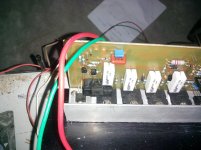
Please help me.
If I have on the power supply then start the burning resistance 100ohms marked as blue suggest me what can I do.
check resistance value are you sure there is 100 ohm 2w resistance?
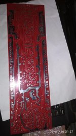
Please check the pcb is this OK or something went wrong please confirm
pcb may be not good .
Thanks rohin for your reply. if you have corrected pcb layout so, please share with me my mail ID is gunjaudio@gmail.com/ 08318685681 whatsapp me.
I will post schematic for PSU and protect soon.
Full power of this amplifier is not 900W. Power with THD 0,5% is 1200W on 4R load, and 1800W on 2R load. Output transistor must be MJL4281A/MJL4302A for maximum power. For step mosfet use IRF2807. MJL21193/MJL21194 can be used for full power on 4R load.
Transformer minimum 1500VA for one channel 4X40V AC + 2X20V for protection circuit. 2X35A bridge and 8X100
00uF/63V for PSU... are you still interesting to build this amplifier?
sir,can I replace 2pair IRF 2807 instead of IRF540??my outputs are MJL4281/4302 total 4 pair.Rail voltage is 4*40v ac..and can i bridge it with this rail voltage ??my subwoofer is 1500watt RMS 8 ohms .is it perfect for my subs??And Thank you for B500 it's nice amp.
sir,can I replace 2pair IRF 2807 instead of IRF540??my outputs are MJL4281/4302 total 4 pair.Rail voltage is 4*40v ac..and can i bridge it with this rail voltage ??my subwoofer is 1500watt RMS 8 ohms .is it perfect for my subs??And Thank you for B500 it's nice amp.
Yes you can, you can bridge with this rail and 8 ohms load.
Dear apex can i use transformer 110..55..0..55..110 volts 10 Amp transformer in this h900 ampl.
Dear apex can i use transformer 110..55..0..55..110 volts 10 Amp transformer in this h900 ampl.
yes you can use for one or two seconds.😱
Dear apex can i use transformer 110..55..0..55..110 volts 10 Amp transformer in this h900 ampl.
No, with 4 output pair use 80-40-0-40-80vac
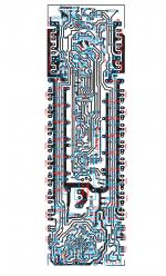
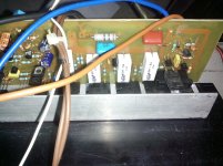
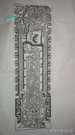
Dear Apex Sir please check and confirm this layout is correct or need any rectification.
Thanks & Regards
Anand Kumar
cont: +918318685681(India)
nice
- Home
- Amplifiers
- Solid State
- 900W H-class PA Amp with Limiter