Re: Re: 811A Schematic #3
Konnichiwa,
Isn't it obvious?
The 811A is operated in "enhancement mode", which means with substantial grid current and the grid positive with respect to ground. At zero volt grid and 600V +B you barely get 5-10mA Anode current. You need to push up the gridvoltage drastically (for a valve) to make this Valve work.
The Valve driving it is a depletion mode device and will lift the 811A Grid a certain amount of voltage, the exact amount of voltage depending upon the current drawn, the more current the less voltage. Thus the grid and the apropriate driver cathode follower valve can be made self balancing and a cathode resistor could be omitted using the right combo.
Just looking at the curves we may have 600V +B, 20V Gridvoltage and 10mA Gridcurrent (all quick guesses) with 80mA Anode current for the 811A. If we whaere to try to double the voltage our gridcurrent would triple, thus safely pulling the grid back down. All we would need is a triode with ~ 20V Bias @ 330V & 10mA.... One might adjust the final bias a little by adjusting the driver valves +B.
BTW, I would always use cathode feedback with this kind of circuit, meaning to loop the speaker side secondary into the cathode of the 811A. This would make the whole Valve have a net gain a lot lower than the 160 or so it has in this operation. The +B decoupling for the Follower should then be bootstrapped from the 811A Cathode as well.
Looking at Shishido's circuit, one could use an OPT around 2K:8R with 100mA current handling and use the 8 Ohm secondary as both cathode feedback winding and output winding. The 425V +B are easily arrived at and we would then only need a follower valve with 25V Bias @ 15mA/appx 400V.
This should then work zero feedback, with a simple SRPP Driver Stage, like the 12AY7/6072A one shown for the other schematic. This would make an 811A Amp on a fair shoestring, with only one coupling capacitor and a cathode capacitor on the 6072A Cathode (22uF Film should do) using a very simple circuit.
Shame I have this irrational fear of using valves with Top-Cap's. It could make a cute litte AMplifier, pretty "bright" too....
Sayonara
Konnichiwa,
dhaen said:
In this design without a path from G1 to ground, I'm intrigued as to what stops the 811 from "running away"...
Isn't it obvious?
The 811A is operated in "enhancement mode", which means with substantial grid current and the grid positive with respect to ground. At zero volt grid and 600V +B you barely get 5-10mA Anode current. You need to push up the gridvoltage drastically (for a valve) to make this Valve work.
The Valve driving it is a depletion mode device and will lift the 811A Grid a certain amount of voltage, the exact amount of voltage depending upon the current drawn, the more current the less voltage. Thus the grid and the apropriate driver cathode follower valve can be made self balancing and a cathode resistor could be omitted using the right combo.
Just looking at the curves we may have 600V +B, 20V Gridvoltage and 10mA Gridcurrent (all quick guesses) with 80mA Anode current for the 811A. If we whaere to try to double the voltage our gridcurrent would triple, thus safely pulling the grid back down. All we would need is a triode with ~ 20V Bias @ 330V & 10mA.... One might adjust the final bias a little by adjusting the driver valves +B.
BTW, I would always use cathode feedback with this kind of circuit, meaning to loop the speaker side secondary into the cathode of the 811A. This would make the whole Valve have a net gain a lot lower than the 160 or so it has in this operation. The +B decoupling for the Follower should then be bootstrapped from the 811A Cathode as well.
Looking at Shishido's circuit, one could use an OPT around 2K:8R with 100mA current handling and use the 8 Ohm secondary as both cathode feedback winding and output winding. The 425V +B are easily arrived at and we would then only need a follower valve with 25V Bias @ 15mA/appx 400V.
This should then work zero feedback, with a simple SRPP Driver Stage, like the 12AY7/6072A one shown for the other schematic. This would make an 811A Amp on a fair shoestring, with only one coupling capacitor and a cathode capacitor on the 6072A Cathode (22uF Film should do) using a very simple circuit.
Shame I have this irrational fear of using valves with Top-Cap's. It could make a cute litte AMplifier, pretty "bright" too....
Sayonara
An amp design for daredevils, perhaps?😉
I guess the driver tube and it´s plate voltage has to be chosen very carefully, especially since there is no bias adjustment pots.
What happens when the driver tube ages?
(I can guess, but it was a rethorical question...🙂)
That´s where my chokes enters the game: Low DC resistance (2/3 of the current through the cathode follower goes straight south and the remaining third goes into the grid) and high AC impedance (doesn´t load the driver stage much).
Shuld stabilize the whole bias situation quite a bit, I think.

Konnichiwa,
Not really.
Yes, choose the tube well, but you can adjust the bias by adjusting the +B of the driver.
The Driver Valves bias will go up and the output Valve will have a bit more grid current, which will pull the driver valve back down to earth... ;-)
Well, the grid presents a dynamic load of around 1k...2k to the driver, so I'd not worry too much about "not loading the driver".... It's well loaded already.
You must stop to think in classic valve biasing terms when you go class A2.... The output Valve suddenly behaves electrically a lot like a high voltage transistor.
Sayonara
Fuling said:An amp design for daredevils, perhaps?😉
Not really.
Fuling said:I guess the driver tube and it´s plate voltage has to be chosen very carefully, especially since there is no bias adjustment pots.
Yes, choose the tube well, but you can adjust the bias by adjusting the +B of the driver.
Fuling said:What happens when the driver tube ages?
The Driver Valves bias will go up and the output Valve will have a bit more grid current, which will pull the driver valve back down to earth... ;-)
Fuling said:That´s where my chokes enters the game: Low DC resistance (2/3 of the current through the cathode follower goes straight south and the remaining third goes into the grid) and high AC impedance (doesn´t load the driver stage much).
Well, the grid presents a dynamic load of around 1k...2k to the driver, so I'd not worry too much about "not loading the driver".... It's well loaded already.
You must stop to think in classic valve biasing terms when you go class A2.... The output Valve suddenly behaves electrically a lot like a high voltage transistor.
Sayonara
Not really.
It was a bit of a joke😎
Yes, choose the tube well, but you can adjust the bias by adjusting the +B of the driver.
I´m looking for suitable tubes in this very minute in case my 6AS7/choke idea by any reason would fail. I guess a big phat reostat in the driver PSU would work fine as a bias control.
The Driver Valves bias will go up and the output Valve will have a bit more grid current, which will pull the driver valve back down to earth... ;-)
...which is pretty much whar I guessed🙂
so I'd not worry too much about "not loading the driver"
I´m not worried about not loading the driver, but to load the driver too much (as might happen if the choke was to be replaced by a resistor, as I´ve seen somewhere)
I think this is a very interesting approach to an "high" power SE DHT amp. Way cooler than just a bunch of 300B´s and 6SN7`s

I expect a lot of heat and a lot of light

Re: Re: Re: 811A Schematic #3
Cheers,
Well it wasn't at the time, otherwise I wouldn't have posed the question 🙄 However it is now that I've notice the anode volts.Kuei Yang Wang said:Konnichiwa,
Isn't it obvious?
The 811A is operated in "enhancement mode", ..snip...Sayonara
Cheers,
Refering to schematic #3:
Suppose we use a fixed B+ for the driver tube, wouldn´t it be possible to use a variable voltage source to set the grid bias for the driver (and therefore also the 811A)?
Seems easier than a variable B+, right?
I´ve been looking for suitable driver tubes, and one that I´ve come up with is 6EW7 (amongst other similar compactrons).
The power section has Rp 800 ohm and Pa 10W, max cathode current is 175 mA.
It also has a low power section which looks (roughly) a bit like half a 6SN7.
I´ve done som serious thinking about this driver stage issue, and
I guess one 6AS7 and one big choke per channel is a bit bulky so I think I´ll give the #3 topology a chance.
Other tubes Ivé been looking at as drivers are:
Triode wired EL86
Paralell 12B4A
A2293
Triode wired EL34
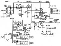
Bias the driver
In this schematic a variable bias is used for the driver tube.
I breadborded this one a few months ago.
Biasing works very well with this setup.
Output was 5W. I did not listen to it because I needed the OPT's
for another project.
Why not use the pentodes as pentode-CF ?
The 12HG7 could also be a good candidate with a GM of 31mS.
Jim
Suppose we use a fixed B+ for the driver tube, wouldn´t it be possible to use a variable voltage source to set the grid bias for the driver (and therefore also the 811A)?
In this schematic a variable bias is used for the driver tube.
I breadborded this one a few months ago.
Biasing works very well with this setup.
Output was 5W. I did not listen to it because I needed the OPT's
for another project.
Other tubes Ivé been looking at as drivers are:
Triode wired EL86
Paralell 12B4A
A2293
Triode wired EL34
Why not use the pentodes as pentode-CF ?
The 12HG7 could also be a good candidate with a GM of 31mS.
Jim
Attachments
Good to hear from a person that has actually built this kind of thing and made it work. I guess the low output power is a consequence of the low plate voltage for the 811A.
I´m aiming for about 430-440V and 8-10W out.
The 12HG7 could be one alternative, but I think I´ll aim for something with a bit higher current cabability. Besides, "my" tube store only has three pieces for sale and I can´t seem to find them elsewhere.
I think I´ll start with EL34´s as drivers, mostly because I have two pairs of Svetlanas in pretty good condition.
807´s would look better next to them 811´s, so maybe I can change later if it works as intended.🙂

Would it be considered blasphemy to use a Mosfet follower as driver stage???
Yes. Too easy and too effective

I use them to drive the screens of my output stage (grounded grid sweep tubes), and they work marvelously well.
mosfet driver
a mosfet driver is very effective indeed, and i found it works well.
my amp: 5687 - IRF840 - 811A
all stages choke loaded
5687 and mosfet have a common low voltage supply (i think 150V or so).
it is easy to adjust quiescent current of 811a with the voltage divider on the mosfet gate, and precise.
i didn't listen much to the amp because it has a heat problem... i will rebuild it as mono blocks. some day.
power output about 12W
easy to get 15W...
I have a good bunch of IRFP460´s, I guess they would be great drivers if the tube approach fails.
I´ve been thinking about these grid currents.
At a given positive grid voltage, the grid current increases with decreasing plate voltage, right?
Wouldn´t that mean that the grid current would be extremly high during startup when the filament is warm and the grid voltage is applied but there is no plate voltage? (Due to slow warmup IDH rectifiers for the plate voltage)
If that is a problem it can be solved by using a delay circuit for the driver HT, but I´m glad I thought about it before I caused some kind of grid meltdown...
fuling,
i don't think so.
look at the datasheet; when plate current is zero (as is the case when filaments are cold), grid current must also be zero.
also it is logical: how could current flow in the tube, when there is no emission, no electrons???
see, there is no problem at startup.
i don't think so.
look at the datasheet; when plate current is zero (as is the case when filaments are cold), grid current must also be zero.
also it is logical: how could current flow in the tube, when there is no emission, no electrons???
see, there is no problem at startup.
I mean when the filament is warm. Since the grid is at +25V I guess there will be a hell of an emission and every single electron will hit the grid since there is no plate current until the rectifier has warmed up?
I read somewhere that the grid cannot take more than 100mA before getting damaged.
I read somewhere that the grid cannot take more than 100mA before getting damaged.
ah yes, when the filament is already warm and b+ is zero, you will get grid current. the grid is at 25V, and it is pretty close to the heater, so it will definitely attract electrons. however, please look at the data sheet. on mine, the lowest curve shows grid current at 20V, it is about 10mA over most of the plate voltage operating area. It rises at low to very low plate voltages, unfortunately it isn't plotted to zero...
but it would have to become VERY steep to hit 100mA... looks more like 30-40mA at zero plate volts. at 40V grid bias, you could hit 100mA grid current.
the maximum rating printed in my datasheet is 50mA.
well, i still think at low grid bias there is nothing to worry about. this condition doesn't last that long anyway, the rectifier will come up and as soon as a few volts (say 20) appear on the plate you are definitely in the safe operating area.
I guess I´ll have to wait and see what really happens in a practical circuit.
Can´t really decide what driver to use...
In my prototype breadboard (still waiting for 811´s) there is a choke loaded EL86 cathode follower which seems to work fine,
but I can see some technical benefits in using Mosfets too.
Can´t really decide what driver to use...
In my prototype breadboard (still waiting for 811´s) there is a choke loaded EL86 cathode follower which seems to work fine,
but I can see some technical benefits in using Mosfets too.
I´m happy to say that my mono prototype is up and running!🙂
The tubes came in the mail today (three weeks later than expected...)
Output power at 460V/100mA 5,6k is 12W, not bad I think!!
Listening impressions are...impressive!
This beast can play LOUD!!
I think I´ll add some local feedback around the output tube to tighten up the bass response a bit.
For now I use a triode wired choke loaded EL86 as driver, but I´ll try a Mosfet some day.
- Status
- Not open for further replies.
- Home
- Amplifiers
- Tubes / Valves
- 811a Class A2