More of for info - push pull 807 triode mode
https://frank.pocnet.net/other/AWV_Radiotronics/ckt/AWV_Amplifier_A515_1947_a.pdf
Cheers,
Ian
https://frank.pocnet.net/other/AWV_Radiotronics/ckt/AWV_Amplifier_A515_1947_a.pdf
Cheers,
Ian
Eli - could you point to a single practical example of a SE pentode amp (commercial or DIY) with output transformer inside the NFB loop?
Eli - could you point to a single practical example of a SE pentode amp (commercial or DIY) with output transformer inside the NFB loop?
Watch the video, for starters. 😉
The cheap SE console amps used either 6V6s or 6BQ5s for roughly 5 WPC.
This 6BM8/ECL82 schematic originated with Mullard.
Touch base with Tom Bavis. His collection of schematics is extensive.
This Edcor O/P trafo is more than hefty enough for a 6L6 family tube. The OP could take advantage of the capability by some "A2" action. However, the "easy" way to do that is with a MOSFET driver, which may not be to his liking. That "iron" could be used for a UL mode final, but a 6SL7 section could be "in over its head" dealing with the increased CMiller.
Thanks for the pointers. I looked into this in more detail. In 50s-60s, there was a lot of SE 6V6 and 6BQ5 amplifiers, mostly in bottom-of-the-line equipment. Some used global NFB, others didn't. Among the latter were some respectable designs, like Siemens Klangfilm. I am wondering how NFB phase shifts were managed with SE output transformers, which have a lot of leakage inductance and winding capacitance?
My inexpensive 1625 SE amp: 6th Street Bridge: Project: The Command 1625 tube amplifier
mostly made with parts from my-then extensive junk box.
I would add in current meters on the output as I had one or two 1625 that was gassy. They would test good, and even operate a time before the current started running away.
mostly made with parts from my-then extensive junk box.
I would add in current meters on the output as I had one or two 1625 that was gassy. They would test good, and even operate a time before the current started running away.
I am wondering how NFB phase shifts were managed with SE output transformers, which have a lot of leakage inductance and winding capacitance?
I'm not sure if they bothered. Tom Bavis' schematic collection would have some answers.
Touch base with Jeff Yourison. He and I worked on a tweaked version of the Mullard 6BM8 design. Our version uses a UL mode "final" and drops the tone controls. Phase compensation is brute force. An inductive WW resistor is used as the voltage amplifier load. The "hot" speaker terminal of the O/P "iron" is connected to ground, via a small capacitor. The cap. is sized to short the NFB loop out above 80 KHz. The inelegant, non test instrument, method works surprisingly well. The natural HF roll off of the O/P "iron" is exploited.
Last edited:
My inexpensive 1625 SE amp: 6th Street Bridge: Project: The Command 1625 tube amplifier
mostly made with parts from my-then extensive junk box.
I would add in current meters on the output as I had one or two 1625 that was gassy. They would test good, and even operate a time before the current started running away.
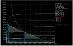
Http://6streetbridge.blogspot.ro/2012/11/project-command-1625-tube-amplifier.html project here, is something very beautiful, but in my opinion I think that the choice of R = 5K is a poor choice, but with R = 8K would be the best load on the power supply.
Major differences between the two graphs same static operating point tubevacuum 807.
Attachments


If you are going SE, Edcor has a nice 15W transformer. I've used quite a few and have been very pleased with them.
This is the 5K : 8 version, they also make a 3.5K : 8 and others.
EDCOR - GXSE15-8-5K
This is the 5K : 8 version, they also make a 3.5K : 8 and others.
EDCOR - GXSE15-8-5K
It depends. According to your analysis, Ra = 8k results in slightly (neglegible!) more Output power @ less THD, which mainly consists of H3 distortion. 5k gives more THD with more H2 than H3, which may sound more pleasant to some ears.
Best regards!
Quite rightly you say, I looked Electric, audiophiles is somewhat difficult to understand
and very subjective in the end.
Best regards!
Or this 25W primary 3750:If you are going SE, Edcor has a nice 15W transformer. I've used quite a few and have been very pleased with them.
This is the 5K : 8 version, they also make a 3.5K : 8 and others.
EDCOR - GXSE15-8-5K
EDCOR - CXSE25-3.75K
Seems these transformers cant have two taps as 4 & 8 ohms, only 1 output.(??)
Or this 25W primary 3750:
EDCOR - CXSE25-3.75K
Seems these transformers cant have two taps as 4 & 8 ohms, only 1 output.(??)
Then ask Edcor about a variant with multiple speaker taps. Of course, it will cost more than a part with a simple secondary.
Perhaps the best solution is to have the trafos made up with a single 6 Ω secondary. Things will be fine, as long as you don't try 16 Ω speakers.
FWIW, I strongly favor the 25 W. "iron". If the urge to try "A2" action strikes, you are ready for the increased power O/P. "Better to be looking at it than needing it."
Last edited:
download complete STC Brimar book 43pg
http://nekhbet.com/STC807.pdf
i built few years ago one amp inspired from the 75 watts one power stage ans sound beautyfull
PP 807 STC
http://nekhbet.com/STC807.pdf
i built few years ago one amp inspired from the 75 watts one power stage ans sound beautyfull
PP 807 STC
FullRangeMan
If you want Fb less sound, then need to use really good, low µ triode and OPT= >10 * ra
If you want Fb less sound, then need to use really good, low µ triode and OPT= >10 * ra
A 10K ohms OPT will be expensive, seems more than 5kg.FullRangeMan
If you want Fb less sound, then need to use really good, low µ triode and OPT= >10 * ra
Do a C core would lower the DHT?
What kind of sound a C core would offer w/a 1625?
FWIW, I strongly favor the 25 W. "iron". If the urge to try "A2" action strikes, you are ready for the increased power O/P. "Better to be looking at it than needing it."
As huge as 300W power transformers. I use them in my GK-71 amp.
A 10K ohms OPT will be expensive, seems more than 5kg.
Do a C core would lower the DHT?
What kind of sound a C core would offer w/a 1625?
Dozens of people told you to avoid this idea
Sorry I missed this one.Dozens of people told you to avoid this idea
I wonder why C core not recomended?
- Home
- Amplifiers
- Tubes / Valves
- 807 Sound Quality?