I placed a parallel large value resistor per euro21's suggestion so the 801A is biased to cutoff until the 6BX7 conducts.
That's a very good idea.
Those Maida regs, are your own design or else?
They are a friend's design, very high performing, something like 110-120dB PSRR. The schematic is a bit misleading though as a single Maida feeds both channels, all stages. Very low output impedance from the regulator.
I made a mental error, did not see the heater pins are switched between 6F5 and 6SF5, so using both in this amplifier will require a simple adapter. I've decided I will build it for 6F5 natively, they are equivalent, however much more variety and availability of 6F5 / 6F5G / 6F5GT / 6F5M over 6SF5.
Got my hands on a set of Sylvania 6F5G, shouldered type. They sound great.

Impressive linearity, like the 6SF5.

Very pleased I came across these and they work well in this design. Going to try and finish the chassis design this weekend.
Got my hands on a set of Sylvania 6F5G, shouldered type. They sound great.
Impressive linearity, like the 6SF5.
Very pleased I came across these and they work well in this design. Going to try and finish the chassis design this weekend.
Yep! 6F5, 6SF5, 6SQ7....all pretty good. I tend to avoid top caps but if that doesn't bother you it's good stuff.
Jeeze, I wonder when you're going to start having some fun !
What kind of fun, Hearinspace? The good kind or the bad kind? 😀 chassis design is coming along in AutoCAD, I've decided I will recess the sockets and do the ventilation like so.

Yep! 6F5, 6SF5, 6SQ7....all pretty good. I tend to avoid top caps but if that doesn't bother you it's good stuff.
I'm okay with the top cap, I'm going to shield the wire, noise floor is essentially identical on the measurements. I like the variety of the 6F5, some interesting options like the MOV H63 or French-made 6F5M. Also some Russian equivalents with very impressive internal construction 🙂
Hi euro21,
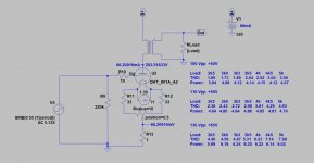
My bias point is slightly negative of 0V for peak symmetrical clipping with a 5K load, 320V 55mA. The grid voltage varies from sample to sample of 801A, but somewhere between -4V to -10V.
Completed simulation of my circuit shows 0.35% THD at 1W into 8ohm with a 5K load, which aligns very well with real-world measurements. With a 3.5K load and no other variables changed in simulation, THD is 0.47% at 1W into 8ohm load. This is with the same degree of NFB - if I were using 3.5K, I would opt for additional NFB lower the output impedance for at least 3:1 damping ratio, so perhaps the THD would be similar. Also, if using a lower Z OPT primary, I would likely alter the bias point similar to your simulation for symmetrical clipping at peak output.
There are many ways to skin a cat 😀 but I won't be changing transformers, I worked with Brian Sowter for the 5K design and I am very happy with how it sounds, but thanks for the info.
I've made great progress this morning on the chassis design, the top plate is nearly complete, which is the most difficult. When designing this way, since all drilling / machining will be done by my friend Dave at Landfall, I include stick diagrams of internal components to scale to optimize the layout. There is just one more thing I need to fit that I had forgotten...it is an iterative process 😛

I put together a nice compact 1mA CCS load for 6F5, IXTP08N100D2 / LND150, 1"x1" footprint.

My bias point is slightly negative of 0V for peak symmetrical clipping with a 5K load, 320V 55mA. The grid voltage varies from sample to sample of 801A, but somewhere between -4V to -10V.
Completed simulation of my circuit shows 0.35% THD at 1W into 8ohm with a 5K load, which aligns very well with real-world measurements. With a 3.5K load and no other variables changed in simulation, THD is 0.47% at 1W into 8ohm load. This is with the same degree of NFB - if I were using 3.5K, I would opt for additional NFB lower the output impedance for at least 3:1 damping ratio, so perhaps the THD would be similar. Also, if using a lower Z OPT primary, I would likely alter the bias point similar to your simulation for symmetrical clipping at peak output.
There are many ways to skin a cat 😀 but I won't be changing transformers, I worked with Brian Sowter for the 5K design and I am very happy with how it sounds, but thanks for the info.
I've made great progress this morning on the chassis design, the top plate is nearly complete, which is the most difficult. When designing this way, since all drilling / machining will be done by my friend Dave at Landfall, I include stick diagrams of internal components to scale to optimize the layout. There is just one more thing I need to fit that I had forgotten...it is an iterative process 😛
I put together a nice compact 1mA CCS load for 6F5, IXTP08N100D2 / LND150, 1"x1" footprint.
Sure thing, I'll post the gerber files and BOM once they are tested, probably cheaper than international shipping from the USA to place a separate order from JLCPCB using the files actually. With HASL finish, it is $5 USD + $13 express shipping for me for a pack of 10.
They are a Chinese company, as far as I know they only ship from China, that is the majority of the cost though, the PCBs themselves are very affordable. They do a good job though with quick turnaround, I would say 1.5-2 weeks from ordering to the door.
After several hours of work, I finished the layout and chassis design, dimensions are 3.25" x 13.5" x 16.5".
Top plate and recessed socket plates.

Front panel.

Rear panel.

Side panels.


The main chassis will be powder coated in a semi-gloss medium gray, the recessed socket plates will be in matte black. Just need to review my old color choices to be certain I won't have a change of heart.
Based on some measurements I was seeing, I've opted to use two Maida regulators, one for each channel. Given the dynamic load in A2, I found this helped keep the operating voltages nice and stiff out to a full 7W into 8ohms. Will halve the power dissipated in the power FETs as well, each will have its own external heat sink mounted on the rear panel.
Top plate and recessed socket plates.
Front panel.
Rear panel.
Side panels.
The main chassis will be powder coated in a semi-gloss medium gray, the recessed socket plates will be in matte black. Just need to review my old color choices to be certain I won't have a change of heart.
Based on some measurements I was seeing, I've opted to use two Maida regulators, one for each channel. Given the dynamic load in A2, I found this helped keep the operating voltages nice and stiff out to a full 7W into 8ohms. Will halve the power dissipated in the power FETs as well, each will have its own external heat sink mounted on the rear panel.
Last edited:
At long last, I got the chassis. Finishing prepping it earlier today, removed powder coating from the mating facing and sanded the interior so as to make a good grounding surface. Now mounting components, here it is so far.

Will post more pictures as the build progresses.
Will post more pictures as the build progresses.
Thanks! Here is progress on the interior. Have just about everything mounted but the transformers. Have to figure out how I am going to arrange terminal strips around the sockets, then wire it all up.


Some progress. Power supply wiring is nearly done. Might be crazy but going to see if I can finish this today.

- Home
- Amplifiers
- Tubes / Valves
- 801A in Single-Ended A2 - Design and Build