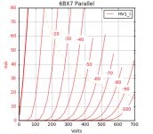
mhh...I still think your main distortion generator is the cathode follower which works into a non-linear load from zip.
To be certain you should try a good source follower, for our peace of mind.....😀
I built it with a source follower in a previous prototype and saw the same high H3 with a lesser H2.
Here is an example, this is with a Cree C2M1000170D source follower, CCS modification on the EF37A, 470K parallel load to ground.
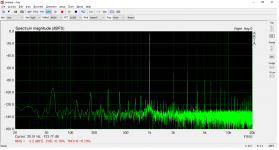
Now compare the same with parallel 6BX7 cathode follower.
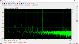
Indeed that's the way to make a decision when unwanted effects (distortion) get small. Forget the spectra....if your primary goal is to build the amp to effectively use it for listening to music.
Thanks for this, I do sometimes tend to fall into measurements nervosa. At the end of the day, I have been listening to this amplifier in my main system for 2 hours, speakers are 92dB/W. It sounds excellent.
If the H3 character is the 801A, I think it is best to accept it for what it is rather than force it into a typical "SET" harmonic profile. Ultimately the amplifier sounds good, so that is most important.
Last edited:
I tend to think it is the output stage SpreadSpectrum, only because I have seen the same in the earlier version of this design which used a Cree SiC follower, shown in the FFT plots above, the high H3 was around in all versions of that prototype as well. The only thing that hasn't changed is the output stage 😛 but as always, I appreciate the feedback.
I am happy with the sound using the 6SF5, the curves are even better than I expected. Should be very simple to make the amplifier 6F5 capable as well, grid at pin 3 moved to the top cap.
I am happy with the sound using the 6SF5, the curves are even better than I expected. Should be very simple to make the amplifier 6F5 capable as well, grid at pin 3 moved to the top cap.
Last edited:
Due to popular demand and to dispel any doubt that the parallel 6BX7 cathode follower is the greatest driver ever put in an A2 design, I put a source follower in one channel and measured the distortion.
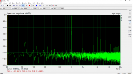
AOT1N60 source follower, wired in as below, 10mA bias with 9K resistor load.
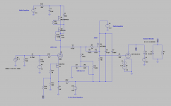
1W into 8ohm FFT
And comparative parallel 6BX7 cathode follower - 1W into 8ohm FFT (y-axis scales are slightly different)
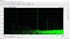
Differences between H2 and H3 are on the order of 1-2dB, probably within error of the measurement, but the high H3 persists with the source follower. I still think it originates in the output stage based on this measurement and what I have seen in the past.
The way I look at it, the 801A in A2 is going to generate H3, so might as well let it be itself and move forward! I like the sound, sad I cannot use my VR105 glow tube with 6SF5 / 6F5, that argon plasma was a real knockout 😛
AOT1N60 source follower, wired in as below, 10mA bias with 9K resistor load.

1W into 8ohm FFT

And comparative parallel 6BX7 cathode follower - 1W into 8ohm FFT (y-axis scales are slightly different)

Differences between H2 and H3 are on the order of 1-2dB, probably within error of the measurement, but the high H3 persists with the source follower. I still think it originates in the output stage based on this measurement and what I have seen in the past.
The way I look at it, the 801A in A2 is going to generate H3, so might as well let it be itself and move forward! I like the sound, sad I cannot use my VR105 glow tube with 6SF5 / 6F5, that argon plasma was a real knockout 😛
Last edited:
Perhaps not entirely due to A2. Try with a 16 ohm load, if H3 drops down then we know the 801 simply wants higher impedance OT. 🙂
Here is the source follower channel at varying outputs into 16ohm secondary. H3 is reduced perhaps 2-3dB at 1W output, remains H3 dominant at low outputs, H2 is increased and overtakes it at higher outputs. I measured the other channel with the 6BX7 cathode follower with identical behavior.
The OPT will not be changed though, I am quite certain 😀
100mW
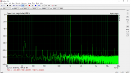
500mW
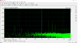
1W
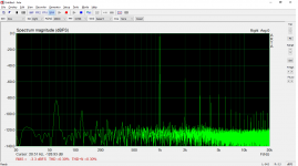
The OPT will not be changed though, I am quite certain 😀
100mW

500mW

1W

Last edited:
For class A2, increasing the primary impedance will drive the tube in a less linear zone as the swing increases and grid current will increase fast....exponentially at some point. Different animal respect to class A1.
Anyway the distortion level we are talking about is low and it might be due it the specific tube in use. It might change with other 801a's..within limits. Who knows? But THD is low enough to not worry about it. It's more technical exercise.
Anyway the distortion level we are talking about is low and it might be due it the specific tube in use. It might change with other 801a's..within limits. Who knows? But THD is low enough to not worry about it. It's more technical exercise.
Last edited:
The only feedback circuits I know are the ones I've tried so far and there is that saying if the only tool you have is a hammer, BUT . . . . . . I wonder what happens to the harmonics if you add some local plate to grid feedback on the 801A. It's a question, not knowledgeable advice.
Agreed, but happy to have verified the 6BX7 is not a major contributor.
There is one outstanding item before I can call the circuit final and design the chassis - the Pete Millett heater regulator I am using on the 6SF5, which is also setting the grid bias, is operating too close to dropout - variations in line voltage affect the regulated output, resulting in bias drift of the 6SF5.
I've used this regulator in the past on the heaters of my phono stage, I improved the line regulation by using lower Vdrop diodes than in the BOM and increasing the capacitance to improve ripple. I will try the same here, otherwise I will need to change regulators. The Tent Labs heater supply I started with had great line regulation, but was very noisy, both audibly and measurably.
The only feedback circuits I know are the ones I've tried so far and there is that saying if the only tool you have is a hammer, BUT . . . . . . I wonder what happens to the harmonics if you add some local plate to grid feedback on the 801A. It's a question, not knowledgeable advice.
I can't comment on that, Hearinspace, as it isn't something I have much experience with but maybe someone else can!
An alternative approach to the 6SF5 bias/heater supply issue...
I need roughly 4.5V in the grid to offset Vgs of the PMOS plus the voltage dropped across the feedback resistor. With the pentode stage, some adjustability was a necessity given how drastically the gain changed by varying the grid bias. But now that a linear triode working into a high impedance load is being used, the grid bias could be fixed by three 1.5V batteries. If the PMOS are reasonably well-matched, any variation in bias point between the two channels will come from variability in the tubes themselves, but a difference of say, 25V on the plates of the 6SF5 should not drastically alter the gain...
I'll give it a try.
My thought was that if the H3 is coming from the output stage and if that in part is due to a low OT primary Z relative to the rp of the tube, that local plate to grid feedback (AKA Schade feedback) in effect reduces the rp and may influence the sound in a positive way .
My only experience with this so far is from building Michael Koster's Meteor design and from a couple of builds using Frank Blöhbaum's circuits previously mentioned. The Meteor with 35tg was not without issue but according to theory, the plate to grid feedback was the reason it worked as well as it did with a 5K output transformer on a tube with rp somewhere more than twice that (around 13KΩ IIRC).
My only experience with this so far is from building Michael Koster's Meteor design and from a couple of builds using Frank Blöhbaum's circuits previously mentioned. The Meteor with 35tg was not without issue but according to theory, the plate to grid feedback was the reason it worked as well as it did with a 5K output transformer on a tube with rp somewhere more than twice that (around 13KΩ IIRC).
The local feedback in the circuit functions in the same capacity as the Schade albeit it compromises two stages instead of one, lowering the output impedance of the 801A, which is around 3.3-3.5K at A2 operating points. This allows it to be paired with a low impedance transformer, 5K on this case. To use the 801A without NFB necessitates a high impedance OPT, on the order of 10-14K. Winding high-turns-ratio transformers like this comes with compromises, typically parasitics leading to poor bandwidth and high copper losses. I tried this initially with one particular transformer, but decided to go the NFB route instead.
The plate-to-cathode feedback will lower the output impedance at the plate of the 801A by a factor of (1+A0*B), where A0 is the open loop gain of the circuit and B (beta) is the feedback fraction. This gets the output impedance at the OPT primary down to around 800ohm from 3K, so we're able to achieve and output impedance of 1.76ohm on the secondary, would be more like 6ohm without NFB.
I am no expert on various feedback topologies, but what I guess I am saying is the Schade feedback and the two-stage local feedback used in this circuit are two means to the same end, lowering the output impedance and bandwidth to be used with a more optimal OPT.
Last edited:
I replaced the heater regulator + bias pot for grid bias on the 6SF5 with batteries. Bought some fancy "Duracell Optimum" at the local pharmacy, seems the secret sauce is higher voltage, they all test at a very consistent 1.692V while being rated for 1.5V (they are AAs). Turn out three in series was a pretty good choice.
With the two 6SF5 I had been using in circuit, with 1mA CCS load, this put 220V on the plate of one and 190V on the plate of the other. Here are the outputs of the two channels overlaid at ~1W into 8ohm.
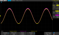
0.25dB difference, which I will never hear. An even more extreme case, I found a more mismatched 6SF5, 220V on the plate of one, 160V on the plate of the other, with the same exact result, 0.25dB between channel outputs. Very likely the mismatch is occurring elsewhere in circuit.
So this seems like a very viable approach, right now the Vgs of the PMOS FETs is not well-matched, which is contributing and can be improved such that any variation in bias is dependent on the tubes themselves. As output falls with age, doesn't seem the end result will be terribly affected.
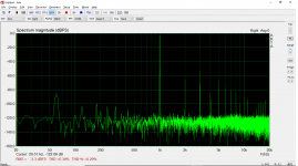
Other than the 60Hz mains coupling, noise floor looks good in this setup. 6BX7 is back in place.
With the two 6SF5 I had been using in circuit, with 1mA CCS load, this put 220V on the plate of one and 190V on the plate of the other. Here are the outputs of the two channels overlaid at ~1W into 8ohm.

0.25dB difference, which I will never hear. An even more extreme case, I found a more mismatched 6SF5, 220V on the plate of one, 160V on the plate of the other, with the same exact result, 0.25dB between channel outputs. Very likely the mismatch is occurring elsewhere in circuit.
So this seems like a very viable approach, right now the Vgs of the PMOS FETs is not well-matched, which is contributing and can be improved such that any variation in bias is dependent on the tubes themselves. As output falls with age, doesn't seem the end result will be terribly affected.
Other than the 60Hz mains coupling, noise floor looks good in this setup. 6BX7 is back in place.

I'm a bit surprised by the lack of difference with source follower. The datasheet curves for 801A indicate that it takes 1.5V more grid drive in the negative direction than in the positive @1W, and the 6BX7 should cause compression on the side that has expansion, changing a 2nd-dominant characteristic into a 3rd-dominant characteristic at 1W. Higher levels look like they would be 3rd dominant to start off.
Of course, this is taking those two stages in isolation. The input stage generates 2nd harmonic in opposite phase, so all of this is highly interactive and hard to predict with rulers and even simulations.
Still, I thought the cathode follower would generate more distortion than it does.
Hearinspace,
In my initial experiments with the 6384 tube, I got nearly identical distortion profiles from equivalent levels of plate-to-grid (Schade feedback) or plate-to-driver cathode feedback. I mean, when I made the measurement I thought there must be something wrong with my setup because the harmonic profiles and distortion levels were so close.
The problem was that even with ~95% Schade feedback I still had more distortion than I wanted (>1%) and the 2 stage solution offers the opportunity to multiply the output tube transconductance by the gain of the previous stage. You effectively make a composite device with much higher transconductance that can reduce distortion further, and you still keep the loop short so it is easy to keep stable and fast. It is a good next step if you find that single stage feedback isn't enough.
They look good, too. They look very similar to the 6BL7s I used in the amp I made for my brother.
They are nice looking tubes, should be a good fit for this amplifier I think, I am going for sort of an 'old school' type of aesthetic.
This circuit is pretty much done as far as I am concerned. I am going to get a handful of the PMOS FETs and match them for Vgs at 1mA current and use battery bias on the input as I mentioned. This way any variation in plate voltage is dependent on the tubes only, and as I saw this variation has little effect on distortion and gain given the linearity of the 6SF5 / 6F5.
So I am going to move on to designing the chassis. Ideas for 'the look' were planned a little while back, so it's more a matter of figuring out the layout. I'll design it in detail in AutoCAD then Dave at Landfall, who has done all of my DIY chassis so far, will do the machining and powder coating. I started doing powder coating at home and told him all about it, this inspired him to get a serious powder coating setup, now it is much better than mine 😛 it's a good thing though because it is a messy business...
Anyway, with that being said, I am planning to go with a semi-gloss medium gray, very boring, but I feel it sort of capture some of that old school industrial tube gear look.
Here is an explanation of some of the parts...
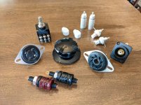
I found this very cool vintage bakelite Kurz-Kasch volume knob, that will pair with the 50K TKD pot.
I have vintage octal and UX4 Amphenol sockets on hand that will go in. I usually bottom-mount for a minimalist type of thing, but I think I am going to top-mount to show them off, again for sort of a utilitarian, industrial-ish look.
Something I haven't done before but will this time - going to put the RCA inputs on the front panel, recessed Amphenol type on the right hand side. Saw this one a Japanese SET amplifier recently, thought it looked pretty cool and keeps the inputs away from the AC.
Binding posts are made by KLE innovations, fit the look I think. I usually include a headphone input with a switch, but think I will skip it this time.
I am going to make the grid top cap leads removable from the chassis, will connect via panel-mounted RCA, cable will be shielded and the RCA shell will be continuous with it. When I was planning to use the EF37A, this was just a flair thing. Now that I am using the 6SF5 / 6F5, it has a functional purpose. The input will be connected to both the panel-mounted RCA and pin 3 of the socket. This way the top-cap can be used with 6F5 and removed when 6SF5 are in use 😀
Last thing to figure out is how I will design the ventilation, nothing flashy, will be very simple, probably circular around the 801A and 6BX7.
Going to take some time to finish the chassis design, very tricky when you don't have the chassis physically in front of you, but worked out well in my last build.
This circuit is pretty much done as far as I am concerned. I am going to get a handful of the PMOS FETs and match them for Vgs at 1mA current and use battery bias on the input as I mentioned. This way any variation in plate voltage is dependent on the tubes only, and as I saw this variation has little effect on distortion and gain given the linearity of the 6SF5 / 6F5.
So I am going to move on to designing the chassis. Ideas for 'the look' were planned a little while back, so it's more a matter of figuring out the layout. I'll design it in detail in AutoCAD then Dave at Landfall, who has done all of my DIY chassis so far, will do the machining and powder coating. I started doing powder coating at home and told him all about it, this inspired him to get a serious powder coating setup, now it is much better than mine 😛 it's a good thing though because it is a messy business...
Anyway, with that being said, I am planning to go with a semi-gloss medium gray, very boring, but I feel it sort of capture some of that old school industrial tube gear look.
Here is an explanation of some of the parts...

I found this very cool vintage bakelite Kurz-Kasch volume knob, that will pair with the 50K TKD pot.
I have vintage octal and UX4 Amphenol sockets on hand that will go in. I usually bottom-mount for a minimalist type of thing, but I think I am going to top-mount to show them off, again for sort of a utilitarian, industrial-ish look.
Something I haven't done before but will this time - going to put the RCA inputs on the front panel, recessed Amphenol type on the right hand side. Saw this one a Japanese SET amplifier recently, thought it looked pretty cool and keeps the inputs away from the AC.
Binding posts are made by KLE innovations, fit the look I think. I usually include a headphone input with a switch, but think I will skip it this time.
I am going to make the grid top cap leads removable from the chassis, will connect via panel-mounted RCA, cable will be shielded and the RCA shell will be continuous with it. When I was planning to use the EF37A, this was just a flair thing. Now that I am using the 6SF5 / 6F5, it has a functional purpose. The input will be connected to both the panel-mounted RCA and pin 3 of the socket. This way the top-cap can be used with 6F5 and removed when 6SF5 are in use 😀
Last thing to figure out is how I will design the ventilation, nothing flashy, will be very simple, probably circular around the 801A and 6BX7.
Going to take some time to finish the chassis design, very tricky when you don't have the chassis physically in front of you, but worked out well in my last build.
I did some thorough A-B listening today of resistor vs. current sink on the 6BX7 cathode follower. The change does not show up in the measurements, at least the ones I use, but the audible difference is large, the current sink is superior undoubtedly, more detail, larger soundstage. I placed a parallel large value resistor per euro21's suggestion so the 801A is biased to cutoff until the 6BX7 conducts. So below is the 'final' circuit, of course small changes could be made along the way, but I feel confident this is 99% done.
Current sink on the 6BX7 will be a single IXCP10M90S, what I used in testing. Changing the cascode CCS load on the 6SF5 to an IXTP08N100D2 with LND150 bottom device given the low bias current. I'll need to design some new CCS PCBs for the TO-92 LND150.
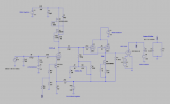
It may not be saying much since I have only built two from-scratch speaker amplifiers and one headphone amplifier, but this is by far the best I have thrown together so far, very excited to get it in my stereo permanently!
Current sink on the 6BX7 will be a single IXCP10M90S, what I used in testing. Changing the cascode CCS load on the 6SF5 to an IXTP08N100D2 with LND150 bottom device given the low bias current. I'll need to design some new CCS PCBs for the TO-92 LND150.

It may not be saying much since I have only built two from-scratch speaker amplifiers and one headphone amplifier, but this is by far the best I have thrown together so far, very excited to get it in my stereo permanently!
Last edited:
- Home
- Amplifiers
- Tubes / Valves
- 801A in Single-Ended A2 - Design and Build
