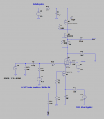
I have been working on an 801A A2 single-ended design for several months. It has reached a point where a performing prototype has been made. I have been posting about it in SpreadSpectrum's "Corona A2" thread, thought I would put an end to the thread spamming and start a new one since the circuit is nearly complete.
The basic topology is as follows:
-Resistively loaded EF37A gain stage, screens regulated by VR105 glow tube
-Cap-coupled parallel 6BX7 cathode follower
-Direct-coupled 801A with near 0Vg1 bias point
-801A plate to EF37A cathode feedback, PMOS buffered
The feedback method is outlined in the Corona A2 thread here: Corona: An Ultra-Low Distortion A2 DHT SE Amp Prototype
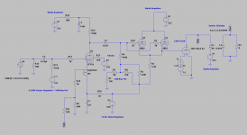
I finished the prototype yesterday, here is the current iteration of the circuit.
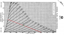
801A load line.
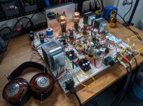
And the prototype on my protoboard. Both the mains and 5K:8ohm transformers are custom from Sowter for this design.
(Side note - I have just learned that Sowter is as of now no longer doing custom mains transformer work, very likely a result of the Carnhill takeover, which is a big loss, this is probably one of the last made, very disappointing...)
Some preliminary measurements.
Output Z: 1.53ohm
Power at onset of clipping: 6.2W into 8ohm
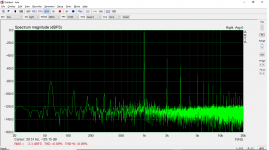
FFT 1W into 8ohm
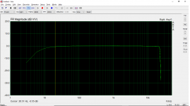
Frequency response
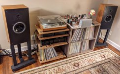
I lugged the prototype into my stereo with my Snell Js, and I must say the sound is very impressive, I would be very happy with it built as is...
But...
There are some things I would like to try before jumping into the chassis design, so I thought I would try those things here, then showcase the final build when the circuit is optimal for me.
-Varying the degree of negative feedback - altering the feedback fraction, pentode load
-FET CCS load on the cathode follower - this will necessitate a time delay circuit to keep the 801A grid happy during startup
-Choke loaded cathode follower - unlikely to try this, as introducing another reactive component could disrupt the feedback stability, but it is in the mix
-CCS pentode load - I have experimented with it in previous iterations to maximize gain of the stage, but may leave the load resistive depending on the resulting harmonic spectrum, using the CCS load previously resulted in an H3 dominant harmonic profile in this circuit, H2 dominant with falling harmonics is preferred
So that is the purpose of this thread, try a few circuit changes, take some measurements, do some listening, then show the final product when it is complete.
DISCLAIMER: I started doing tube DIY January of 2020, I am not an engineer, I work in healthcare, there is much I still do not know. I like to take a learn-by-doing approach and experiment with more complex circuits as I go, I am very much indebted to more experienced and knowledgeable DIYers here (audiowize, SpreadSpectrum, euro21, Rod Coleman, Ale Moglia, to name a few), I am grateful for their help, please be kind
The basic topology is as follows:
-Resistively loaded EF37A gain stage, screens regulated by VR105 glow tube
-Cap-coupled parallel 6BX7 cathode follower
-Direct-coupled 801A with near 0Vg1 bias point
-801A plate to EF37A cathode feedback, PMOS buffered
The feedback method is outlined in the Corona A2 thread here: Corona: An Ultra-Low Distortion A2 DHT SE Amp Prototype
I finished the prototype yesterday, here is the current iteration of the circuit.

801A load line.

And the prototype on my protoboard. Both the mains and 5K:8ohm transformers are custom from Sowter for this design.
(Side note - I have just learned that Sowter is as of now no longer doing custom mains transformer work, very likely a result of the Carnhill takeover, which is a big loss, this is probably one of the last made, very disappointing...)

Some preliminary measurements.
Output Z: 1.53ohm
Power at onset of clipping: 6.2W into 8ohm
FFT 1W into 8ohm

Frequency response

I lugged the prototype into my stereo with my Snell Js, and I must say the sound is very impressive, I would be very happy with it built as is...

But...
There are some things I would like to try before jumping into the chassis design, so I thought I would try those things here, then showcase the final build when the circuit is optimal for me.
-Varying the degree of negative feedback - altering the feedback fraction, pentode load
-FET CCS load on the cathode follower - this will necessitate a time delay circuit to keep the 801A grid happy during startup
-Choke loaded cathode follower - unlikely to try this, as introducing another reactive component could disrupt the feedback stability, but it is in the mix
-CCS pentode load - I have experimented with it in previous iterations to maximize gain of the stage, but may leave the load resistive depending on the resulting harmonic spectrum, using the CCS load previously resulted in an H3 dominant harmonic profile in this circuit, H2 dominant with falling harmonics is preferred
So that is the purpose of this thread, try a few circuit changes, take some measurements, do some listening, then show the final product when it is complete.
DISCLAIMER: I started doing tube DIY January of 2020, I am not an engineer, I work in healthcare, there is much I still do not know. I like to take a learn-by-doing approach and experiment with more complex circuits as I go, I am very much indebted to more experienced and knowledgeable DIYers here (audiowize, SpreadSpectrum, euro21, Rod Coleman, Ale Moglia, to name a few), I am grateful for their help, please be kind
Last edited:
Thanks, SpreadSpectrum, hoping for a good end result.
I made a few observations this morning.
For one, using a resistive load, open-loop gain of the EF37A stage seems to be optimum with around 220K, with a voltage gain of around 110. This results ~0.8% THD H2 dominant at 1W into 8ohm, similar to what is seen in the measurements of my first post. I'll try a few different loads between 200K and 300K to find the best result. In previous iterations, I was unable to generate enough gain in the pentode stage for a suitable output Z with a resistive load (without using an electrolytic bypass cap on the cathode). Now that is not a problem using the PMOS buffer and higher performing output transformers.
Next, I revisited the CCS loaded pentode and took some distortion measurements.
Here is 1W into 8ohm with a FET CCS load and 220K resistor paralleled to ground. As you can see, H2 falls dramatically. However, as observed in previous experiments, the other harmonics are reduced disproportionately and the profile becomes H3 dominant, even more significantly at lower outputs. This had a negative effect on the sound, subjectively, I'll give it another listen before I throw out the idea.
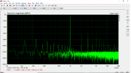
Just for kicks, here is 1W into 8ohm with a FET CCS load and 470K resistor paralleled to ground. In this iteration, open-loop voltage gain of the EF37A approaches 460 and bias drift starts to become an issue, which is something I would like to avoid dealing with.
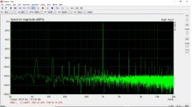
So, despite the impressive distortion numbers of the CCS, I think the resistive load will end up being preferred, but will give it another listen to be certain.
We'll see if any improvements can be made by altering the cathode follower load, that will be next.
I made a few observations this morning.
For one, using a resistive load, open-loop gain of the EF37A stage seems to be optimum with around 220K, with a voltage gain of around 110. This results ~0.8% THD H2 dominant at 1W into 8ohm, similar to what is seen in the measurements of my first post. I'll try a few different loads between 200K and 300K to find the best result. In previous iterations, I was unable to generate enough gain in the pentode stage for a suitable output Z with a resistive load (without using an electrolytic bypass cap on the cathode). Now that is not a problem using the PMOS buffer and higher performing output transformers.
Next, I revisited the CCS loaded pentode and took some distortion measurements.
Here is 1W into 8ohm with a FET CCS load and 220K resistor paralleled to ground. As you can see, H2 falls dramatically. However, as observed in previous experiments, the other harmonics are reduced disproportionately and the profile becomes H3 dominant, even more significantly at lower outputs. This had a negative effect on the sound, subjectively, I'll give it another listen before I throw out the idea.

Just for kicks, here is 1W into 8ohm with a FET CCS load and 470K resistor paralleled to ground. In this iteration, open-loop voltage gain of the EF37A approaches 460 and bias drift starts to become an issue, which is something I would like to avoid dealing with.

So, despite the impressive distortion numbers of the CCS, I think the resistive load will end up being preferred, but will give it another listen to be certain.
We'll see if any improvements can be made by altering the cathode follower load, that will be next.
Last edited:
I replaced the 3.3K 6BX7 cathode follower load with IXCP10M90S / DN2540 current sink set to 28mA. I recognize this is overkill but had the boards filled already, the IXYS FET alone would work very well I think.
There were no measurable improvements in terms of distortion, but I did A-B against the resistive load and did feel the sound was improved with the current sink in place, so I will likely make the change and include it in the final circuit.
The advantage of the resistive load is the 801A is biased into cutoff by the negative supply during startup, until the 6BX7 is heated and begins to conduct. Using a CCS instead, in order to save the 801A grids from flopping in the breeze during startup, I put a relay-switched 30s time delay circuit in between the reservoir cap and the Maida regulator. The regulator has built in soft start as well, so full B+ isn't applied for 45-60s, at which point the 6BX7 is heated, the CCS is switch on with B+ application, and the 801A can come gently up to bias.
I have continued listening while doing A-B testing with 220K resistive load on the EF37A, and I must say the amplifier really does sound fantastic, trying to reconcile that with 1% THD at 1W maybe I like the sound of distortion.
There were no measurable improvements in terms of distortion, but I did A-B against the resistive load and did feel the sound was improved with the current sink in place, so I will likely make the change and include it in the final circuit.
The advantage of the resistive load is the 801A is biased into cutoff by the negative supply during startup, until the 6BX7 is heated and begins to conduct. Using a CCS instead, in order to save the 801A grids from flopping in the breeze during startup, I put a relay-switched 30s time delay circuit in between the reservoir cap and the Maida regulator. The regulator has built in soft start as well, so full B+ isn't applied for 45-60s, at which point the 6BX7 is heated, the CCS is switch on with B+ application, and the 801A can come gently up to bias.
I have continued listening while doing A-B testing with 220K resistive load on the EF37A, and I must say the amplifier really does sound fantastic, trying to reconcile that with 1% THD at 1W
Sorry, I read superficially, and I think, that CCS implemented as CF load.
If there use -large- resistor paralleled with CCS, the output tube grid has enough negative bias to shutting down while CF tubes not conducting completely, and after it biasing neatly.
It's also the safety solution, if CF tube defecting and not properly biasing output tube.
If there use -large- resistor paralleled with CCS, the output tube grid has enough negative bias to shutting down while CF tubes not conducting completely, and after it biasing neatly.
It's also the safety solution, if CF tube defecting and not properly biasing output tube.
Last edited:
The PMOS buffer gets rid of all current feedback in the input stage, which is a really good thing. The current feedback is problematic in pentodes since screen current is mixed in there, and that is going to mess up the feedback and add distortion. Getting rid of it makes it so you can get more gain for feedback that doesn't have screen current mixed into it.
It looks like resistive loading may be best for this particular combination, which is nice since resistors are simple.
If I had to guess, I'd say that with higher impedance loads on the pentode you are approaching a point where the 2nd harmonic generated by the input stage is 180 degrees out of phase with the 2nd harmonic generated by the output stage and there is a lot of cancellation going on.
I never saw this with the 6BN11/826 combo. Every time I increased gain in the input stage, 2nd harmonic stayed the dominant distortion product. I'm guessing the 826 just produces much more 2nd than the 6BN11. 801A seems to be a lower distortion tube than the 826 when I glance at the curves.
Sorry, I read superficially, and I think, that CCS implemented as CF load.
If there use -large- resistor paralleled with CCS, the output tube grid has enough negative bias to shutting down while CF tubes not conducting completely, and after it biasing neatly.
It's also the safety solution, if CF tube defecting and not properly biasing output tube.
Thanks, euro 21, I'll give it a try. Any reason to be concerned about bias drift due to grid current with this high value resistor in parallel?
I changed the EF37A plate resistor to 270K, seemed to give a hair more open-loop gain over 220K with diminishing returns over 270K.
Here is THD into 8ohms at various output levels.
100mW
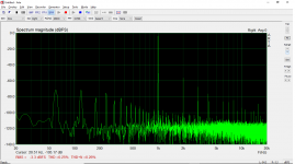
500mW
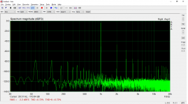
1W
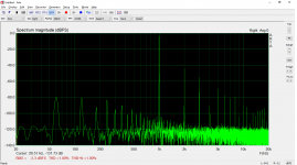
2W
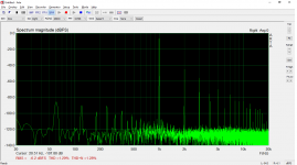
4W
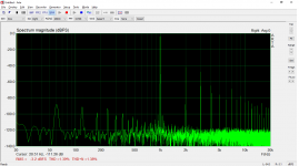
While distortion is high at lower outputs, it is predominantly H2 and doesn't seem to get excessive at higher outputs. I think I can live with these numbers, it certainly passes the ear test.
Here is THD into 8ohms at various output levels.
100mW

500mW

1W

2W

4W

While distortion is high at lower outputs, it is predominantly H2 and doesn't seem to get excessive at higher outputs. I think I can live with these numbers, it certainly passes the ear test.
Last edited:
The PMOS buffer gets rid of all current feedback in the input stage, which is a really good thing. The current feedback is problematic in pentodes since screen current is mixed in there, and that is going to mess up the feedback and add distortion. Getting rid of it makes it so you can get more gain for feedback that doesn't have screen current mixed into it.
It looks like resistive loading may be best for this particular combination, which is nice since resistors are simple.
If I had to guess, I'd say that with higher impedance loads on the pentode you are approaching a point where the 2nd harmonic generated by the input stage is 180 degrees out of phase with the 2nd harmonic generated by the output stage and there is a lot of cancellation going on.
I never saw this with the 6BN11/826 combo. Every time I increased gain in the input stage, 2nd harmonic stayed the dominant distortion product. I'm guessing the 826 just produces much more 2nd than the 6BN11. 801A seems to be a lower distortion tube than the 826 when I glance at the curves.
The PMOS is the secret sauce it seems, open loop gain of the EF37A is only ~115, but I was only able to sniff that gain in the first iteration of this amplifier using an electrolytic bypass cap, which killed the clarity.
Interesting on the distortion cancellation, the difference is pretty huge, but one of those situations I think where the measurements don't tell the whole story, the sound is much better with the resistive load and higher distortion. I knew that in the past, but the high output Z kept me from moving forward.
The waterfall harmonic profile and low distortion you are getting with the 826 seems to be the perfect combination, very curious to hear how it sounds when all is said and done.
Last edited:
As this is prototype I would try a different input stage. Two triodes in cascade for example, which you could actually test separately and set-up for low distortion...and then start from there in the amp. I don't remember the EF37 to be a real "HiFi tube"...
If I look at a pentode distortion profile in SE, the 2nd harmonic will have a null while 3rd is monotonically increasing as function of the load. So, looking at your distortion comparisons between pure resistive and CCS mod, some amount which also affects the other harmonics could be cancellation and the rest could be because you found the 2nd harmonic null when using the CCS.
If I look at a pentode distortion profile in SE, the 2nd harmonic will have a null while 3rd is monotonically increasing as function of the load. So, looking at your distortion comparisons between pure resistive and CCS mod, some amount which also affects the other harmonics could be cancellation and the rest could be because you found the 2nd harmonic null when using the CCS.
Last edited:
Hey 45, I was thinking the same, that some experimentation in the input stage is warranted. I had expected to achieve higher open loop gain with the EF37A, the degree of feedback is less than ideal as a result. Will give some thought to alternative approaches, e.g., triodes in cascode.
Any reason to be concerned about bias drift due to grid current with this high value resistor in parallel?
The effect of the parallel resistor is marginal (few hundred uA peek through the resistor) versus the 801a grid current in A2 mode (few ten mA peek)...if the CF is working properly (low impedance output).
BTW I prefer source follower in this situation, because it's exempted from (CF) tube aging -bias shifting- and output impedance only few Ohms.
Disadvantage, that if FET is dead, mostly shorting.
I use only slightly larger (for example +80..100V) positive supply for FET as targeted A2 peek grid voltage, and usually use small, low wattage "grid stopper" as a fuse.
801a sustain -for a short time- even 40mA grid current if grid voltage +100V (at about 300V a-c voltage), so -for example- small size 100R grid stopper resistor hopefully smokes earlier than tube destroys.
The other source of distortion could be the cathode follower. It's not its load but it's limited gm in comparison to MOSFET. It can deliver the current but it's distorted somewhat. The distortion is proportional to Zout so even if you put a CCS load distortion will not be removed. With 2 6BX7 in parallel you can't match a good source follower. Because your amp is a true A2 this shows up at low output power already.
Duly noted on the parallel resistor, euro21.
I know the source follower has many advantages, previous version of this amplifier used a source follower, Cree C2M1000170D, with a 100ohm 1/4W resistor on the 801A grid to act as a fuse in case of a short. The distortion profile in that version was quite similar to this one, I'm sure I could dig up the FFT, they are stored somewhere...
But I want to use a cathode follower, call it an desire for an 'old school' design, hence the glow tube voltage regulator as well. Some additional gain on the input lowers the distortion appropriately, as can be seen when biasing the EF37A to lower plate voltage, which increases open-loop gain to 130-140.
The EF37A is an audio pentode, precursor to the EF86, and near-equivalent to 6J7. One thought is to use EF86 for some additional gain, with a switch to VR150 for screen regulation.
I know the EF37 is the precursor of the EF86 but there are more linear pentodes. Anyway with 2 triodes in cascade you might find life easier, Set the second triode for best linearity as this is the one delivering the large output and play with the anode load and current of the first to cancel distortion (between the 2 stages or overall).
P.S. Try with the 2 triodes DC coupled first. If need to meet supply restriction can use 2 double triodes where the first can run at lower voltage. So you use half of each per channel.
P.S. Try with the 2 triodes DC coupled first. If need to meet supply restriction can use 2 double triodes where the first can run at lower voltage. So you use half of each per channel.
Last edited:
- Home
- Amplifiers
- Tubes / Valves
- 801A in Single-Ended A2 - Design and Build
