Recommend starting with 'Thinking Fast and Slow,' cover to cover. The reference section is important in all the books, sometimes its a third of what was written. Tetlock, 'Superforecasting' is the latest, important to know something about 'Expert Judgement.' Stanovitch can be found by searching for 'disrationality.' Nisbett, 'Mindware,' an offering of tools to assist.
Kahneman is probably quoted because his work applies to many developments, his Nobel Prize was for Judgement and Decision Making as applied to economics and economic modeling.
Thanks a lot for these. Adding to the pile...
Question about capacitors
On page 58 of the evaluation board's manual, many of the 10µF capacitors (C82, C84, C25, C28, C83, C85, C18, C26, C93, C86, C23, C22, C94, C87, C49, C50) are marked as ceramic capacitors, but they look like they are electrolytic capacitors (similar to the 470µF located close to the DAC chip). The 10µF C1, C2, and C15 are properly marked as electrolytic capacitors and look exactly the same.
Furthermore, on page 106 of the datasheet, all these capacitors are clearly marked as electrolytic capacitors.
Is it fair to assume that all 10µF capacitors on the board should be electrolytic, with the same characteristics?
If so, I am planning to use the 50SVPK10M for all these.
Note: I just realized that the datasheet was using 2200µF capacitors on the VREF circuits! I'm glad they eventually found out that pairs of 470µF would be sufficient...
Libraries for all the components required for the DAC board have been painstakingly created.
We're now ready to work on the schematic.
Here comes the fun part...
On page 58 of the evaluation board's manual, many of the 10µF capacitors (C82, C84, C25, C28, C83, C85, C18, C26, C93, C86, C23, C22, C94, C87, C49, C50) are marked as ceramic capacitors, but they look like they are electrolytic capacitors (similar to the 470µF located close to the DAC chip). The 10µF C1, C2, and C15 are properly marked as electrolytic capacitors and look exactly the same.
Furthermore, on page 106 of the datasheet, all these capacitors are clearly marked as electrolytic capacitors.
Is it fair to assume that all 10µF capacitors on the board should be electrolytic, with the same characteristics?
If so, I am planning to use the 50SVPK10M for all these.
Note: I just realized that the datasheet was using 2200µF capacitors on the VREF circuits! I'm glad they eventually found out that pairs of 470µF would be sufficient...
Last edited:
...just realized that the datasheet was using 2200µF capacitors on the VREF circuits! I'm glad they eventually found out that pairs of 470µF would be sufficient...
What makes you sure they are sufficient? Did you look at page 28 of akd4499-b0-01e ? Also, did you look underneath the dac chip daughterboard?
Last edited:
What makes you sure they are sufficient? Did you look at page 28 of akd4499-b0-01e ? Also, did you look underneath the dac chip daughterboard?
Great points! Not yet. I have yet to procure a Windows XP machine to run the evaluation board...
Next time you look underneath the DAC chip's daughterboard, please make sure to share some pictures. I'll take some as well as soon as I remove it.
The document you mentioned is on the CD, right?
Great points! Not yet. I have yet to procure a Windows XP machine to run the evaluation board...
Next time you look underneath the DAC chip's daughterboard, please make sure to share some pictures. I'll take some as well as soon as I remove it.
The document you mentioned is on the CD, right?
Yes, on the CD. Its just an updated version of the eval board manual. Only change I know of is the page I mentioned.
You don't need XP, the eval board manual says Win7 32-bit can work (maybe needing to use XP compatibility mode). Either that or use Arduino, which works just as well and can be assembled for pretty cheap. I have Arduino code which is very elementary, but it can do everything needed. Happy to share the code, and or to describe the Arduino hardware setup.
I got the files from the CD. I will study them carefully.
Thank you for the offer regarding the Arduino setup, but I think Windows will be a bit easier and will let me use the software that came with the board. So I need to procure a Win7 32-bit machine. A bit sad for a 2019 top-of-the-line DAC chip though...
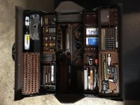
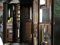
ishizeno, I've been peeking at this thread for a while now and have evenAt the time, I was interested in learning about aluminum profiles. Not just the profiles themselves, but the entire system that is built around them, especially the fasteners. Item in Germany makes the best components that I know. So I decided to give myself an insane project that would give me the opportunity to learn a lot about this system, while making some kind of tribute to my friends. The idea was to build an iPod on wheels (see pictures). Yes, it was as crazy as it sounds...
The whole thing was made out of aluminum, and when the doors and top panels were closed, you could not see a single fastener from the outside. The Power Mac was mounted on a miniature version of the ball bearings used for the rotating ladder on a fire truck engine. And the doors, themselves mounted on geared aluminum profile hinges and softened with pneumatic pistons, could be unlocked with the same keypad used to protect access to an airliner's cockpit post September 11. A pretty decent integrated amplifier was mounted vertically on the back of the aluminum display, and the loudspeakers themselves were made out of milled aluminum.
The whole thing ended up costing more than an entry-level car, and was over 400 pounds.
From a product design standpoint, it was a total disaster.
amazed at your unflappable attitude, forging forward into this complex
project. Good on you!
Looking at your 'total disaster ipod on wheels' experiment, you appear not to be a person that does things by halves. 🙂
The whole thing makes absolutely no sense at all. It's ridiculous, bordering on the obscene. But it was one of the best learning experiences I ever put myself through. Why? Because in order to make it work (sort of), I had to learn everything about every single product sold by Item (there are literally thousands of them). I had to develop a really deep understanding of the different fastening techniques, the pros and cons, and when to use them. And I got to do that because I started with an insane set of constraints (like no visible fastening elements).
We all learn in different ways, I'm sure many people would be overwhelmed by your approach, but I've also seen some great ideas come from extreme
and unorthodox approaches.
This monstrosity was nothing more than a science project, but it taught me some really valuable engineering lessons. And it gave me a really good feel for how to work with aluminum.
Aluminium is a beautiful material with many benefits but also a few things to be careful about. Having worked in various (electro +) mechanical design fields for > 30 years, IMV getting a real understanding of the material you are working with through practical experience, is a definite advantage.
Yesterday, two friends of mine who started an intelligent vision company called me to ask me which robotic arm they should use in order to move a camera around some objects they need to train their artificial vision system against. Thanks to the experience acquired through this insane project, I told them that a robotic arm was probably not the best way to go about solving their problem. Instead, we used the Item aluminum profiles to design a fixed gantry for a matrix of 9 or 16 GoPro cameras, and the only moving part is a turntable on which the scanned object will rest. Without having gone through the process of working on my silly project, I would never have been able to give them this piece of advice, and they might have gone down the rabbit hole of trying to use a robotic arm (the one they were considering had a meter-long reach and was powerful-enough to kill someone if programmed wrong).
Anything robotic and with potential to cause harm, also implies implementation with completely different and more stringent safety
standards. They were heading down a potentially expensive design path. 🙂
So this brings me to some questions about this project which probably should have been asked quite some time ago:
- What is the main usage for this AD / DA / hardware / software / control etc package that you envisage?
- If recording, by whom? Would it be a commercial product aimed at Pro Audio applications or is it more for for amateur / home recording musicians?
- Will it be integrated with other hardware and software?
A fair component of my work is in the Pro but also Home audio recording sector and know the users and the way they work well. One observation is
people who use this gear often have limited technical understanding of it.
As an example, one of the best recorded albums I own was done by a very talented musician client that would struggle to follow a simple flow chart.
This is very common with extremely creative people, they often approach things and work in ways that are intuitive but not necessarily technically correct.
So, I think, obviously depending on your targeted user, it has to be extremely simple and intuitive to use.
PS, apologies if you have previously explained all this. Please point me to a post / page.
T.
ishizeno, I've been peeking at this thread for a while now and have even
amazed at your unflappable attitude, forging forward into this complex
project. Good on you!
Terry,
Thanks a lot for the kind words, very much appreciated.
Regarding your question, I must admit that I do not know the answer myself.
This project is not driven by any kind of market research, and the target audience beyond myself is very much a moving target. The reference setup is a patchwork designed to provide all the controls and interfaces that I would like to get at my fingertips, but other users will most likely design something very different that will best suit their particular needs. The primary objective of the overall project is to demonstrate the versatility of the architecture, without making too many compromises regarding sound quality.
That being said, because of the extreme complexity of the architecture, I doubt that a brain-dead plug-and-play user experience could be provided initially. There are so many layers to the system that developing such an easy-to-use system will probably require massive investments on the software side. That being said, I remain hopeful that we could build something good enough for an audience larger than one...
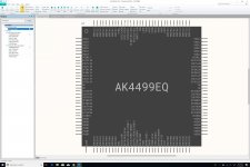
Clearly, the resulting system is not the primary purpose of this insane project. Instead, what truly matters is the project's by-products and side effects. First and foremost, the learning experience for all involved. My hope is that developing this project with an open source approach will make a lot of knowledge available to all. And doing that with fairly exotic components like the AK4499EQ makes this knowledge even more valuable. Testing an MCU-alternative to the XMOS is another positive by-product: if it's demonstrated to work, it could be a major benefit for many designers. And I won't go into the many aspects of sound synthesis that will be covered by the project, because it's not the primary focus of this thread (nor its forum), but this is possibly the area where the most interesting innovation will take place (if I find the time to work on it that is).
Another interesting aspect is the holistic approach that I am trying to take: I am not just focused on the electronics side of things, but also the mechanical aspects, the user interface, the system control, etc. My hope is that developing such a multi-faceted project in the open will inspire others to look more closely at different aspects of product development. Making it sound good is one thing, but a lot more goes into the development of a good product.
Bottomline: the target audience is the one that will recognize itself in some aspects of the project. So far, it's a tiny audience of one, but that's all I need to keep going...
Cheers mate!
Aluminium is a beautiful material with many benefits but also a few things to be careful about. Having worked in various (electro +) mechanical design fields for > 30 years, IMV getting a real understanding of the material you are working with through practical experience, is a definite advantage.
I could not agree more...
Last year, I wanted to learn more about wood in order to make the side panels for my original design. I bought a product from Hekseskudd, then asked their designer if he could train me. I spent a couple days in his basement in Vancouver learning how to use a large-scale ShopBot CNC router and getting a crash course on the processing of black walnut. Equipped what that knowledge, I went on designing and fabricating a whole bunch of trays for my tools (see attached pictures). This gave me a good appreciation for two things:
- Wood is not stable over time.
- The hardest part of the job is the sanding.
For this audio project, the trays (where one can mount six plates, each plate having nine bricks) will have a bottom made of black walnut, but this bottom layer will be mounted on a CNC-machined aluminum frame in order to give sufficient rigidity to the overall assembly. This is massively overkill of course, but it will give mass to the system, hence improve its overall feel of solidity.
The walnut layer will be attached to the aluminum frame with four machined screws that will also serve as mounting structure for four circular cork pads. That way, the walnut underside of the tray will not be scratched and vibrations will be further dampened. But because these cork pads will be mounted on screws instead of directly gluing them to the walnut boards, it should be easy to replace them (cork does not last forever, unlike wood or aluminum).
I liked the CNC part so much that I later enrolled to a local community college for the whole Summer. There, I spent my days with kids learning how to use a lathe and a mill, manual first, then CNC. This was one of the best experiences of my life. And it gave me a much better feel for what can be done with aluminum. I then used that knowledge to design my balanced 6-axes machine, but this project is not something that I can fund myself yet, unlike the planned sound system, so it's in the backburner for now. Also, by doing all that work, I learned more about additive manufacturing and realized that the future is in blending subtractive and additive into fully autonomous cells (the latest HP 3D steel printer and a linear DMG MORI center will be the core components of this cell, with a six-axis arm in between them). But all this is for another forum...
Attachments
Last edited:
Using the right bricks, one should be able to build:- What is the main usage for this AD / DA / hardware / software / control etc package that you envisage?
- a really high-end audio recording, mixing, and mastering console.
- virtually any kind of synthesizer (analog, digital, integrated, modular, East Coast, West Coast, etc.).
- virtually any kind of control surface (for things like lighting control for example).
- If recording, by whom? Would it be a commercial product aimed at Pro Audio applications or is it more for for amateur / home recording musicians?
Probably a professional interested in experimenting with different workflows. For example, the ability to store massive amounts of data (72TB on my planned reference setup) and to do multi-level stem mixing can totally change the way one would approach mixing and mastering.
- Will it be integrated with other hardware and software?
It has to. The first Digital Audio Workstation (DAW) that will be supported is Ableton Live, because that is the one that I am using and like the most (this piece of software is positively awesome). We'll make all the integration open source, which means that anyone should be able to develop drivers for other DAWs.
As far as hardware is concerned, we will probably add digital input and output ports to the ADC and DAC bricks now that we have a bit more space to play with. And we'll make a MIDI brick as well.
The one protocol that I am not sure about is DANTE, because it requires a license, and it probably requires an FPGA to be handled properly. I am totally fascinated by FPGAs, but I am scared by them as well, because I know that if I get into them, it could be a massive time sucker. There is a lot that can be done by a motivated soul, but there is also an upper limit to what a single person can achieve in one's lifetime, and being good at FPGA synthesis is probably something that takes a pretty significant time commitment, at the exclusion of many other things. Therefore, I'll probably skip that step until I can convince myself otherwise, or be in a position to hire an expert for that particular project.[/QUOTE]
As an example, one of the best recorded albums I own was done by a very talented musician client that would struggle to follow a simple flow chart.
This is very common with extremely creative people, they often approach things and work in ways that are intuitive but not necessarily technically correct.
So, I think, obviously depending on your targeted user, it has to be extremely simple and intuitive to use.
Based on my personal experience, if one can master a complex piece of software like Ableton Live or any other modern DAW, one should be able to use our system once we have a proper driver for it.
If we do our job right, the USB plates will be totally plug-and-play, therefore should be easy to use. The OTOBUS™ bricks will be a different story. For these, one might have to do a fair bit of configuration at the MCU level in order to get them working properly. Therefore, it's probable that we'll get two kinds of users: more technically-oriented ones developing their own plate-level instruments out of off-the-shelf bricks, and less techno-savvy ones using pre-built plate-level instruments to compose their own surface using one or multiple trays.
And an unambiguous mark of success for the project is when people will develop their own custom OTOBUS™ bricks...
Last edited:
What makes you sure they are sufficient? Did you look at page 28 of akd4499-b0-01e ? Also, did you look underneath the dac chip daughterboard?
I am looking at the chart of page 28 (THD+N over Frequency), and here is what I get out of it: up until 700Hz, the best configuration is 470µF for C90, C6, C35 and C14, and 0Ω for the series resistors. But above 700Hz, larger capacitance and 10Ω is the way to go, with 3,300µF providing the best results, while 2,200µF gets really close (2 to 3dB worse than 3,300µF at 20Hz).
If so, it seems to me that if we stick to 470µF, we really have to consider whether we go for 0Ω or 10Ω for the resistors, because at low frequencies, the difference is quite significant (over 20dB), while it's very small at high frequencies (around 2dB).
Therefore, the two best options seem to be:
1. 2,200µF and 10Ω (best trade-off)
2. 470µF and 0Ω (pretty darn good still)
Did I get that right?
And now I am really curious about whether a circuit could bring the best of both worlds: what option #1 has to offer above 700Hz and what option #2 brings below 700Hz... 😉
Last edited:
Did I get that right?
One rather significant issue, IMHO. The graph only tells us about measured harmonic distortion. Could there be any other possible audible effects besides that? One good start might be to try listening, short across the 10-ohm resistors and listen again. Add some more caps and...
My bet would be you will find out there is more to the story than you know so far.
Multiple capacitors in parallel
If we decided to go for the largest possible capacitance for C90, C6, C35 and C14, we probably would have to use pairs of 1,200µF capacitors mounted in parallel, because this is the maximum capacitance offered by surface-mounted Panasonic OS-CON capacitors above 4V. The 16SVPK1200M are small enough that we should be able to put eight on the top side of the board, really close to the DAC chip, as long as the DAC chip is properly positioned on the board (probably rotated by 90° compared to what I had originally envisioned). This thread possibly suggests that this should be acceptable, unless a lower ESR would result in some instability. The ESR for a single 16SVPK1200M is already a very low 12mΩ. Therefore, with two in parallel, it would be 6mΩ. But if it works, it would give us 2,400µF of total capacitance.
If we decided to go for the largest possible capacitance for C90, C6, C35 and C14, we probably would have to use pairs of 1,200µF capacitors mounted in parallel, because this is the maximum capacitance offered by surface-mounted Panasonic OS-CON capacitors above 4V. The 16SVPK1200M are small enough that we should be able to put eight on the top side of the board, really close to the DAC chip, as long as the DAC chip is properly positioned on the board (probably rotated by 90° compared to what I had originally envisioned). This thread possibly suggests that this should be acceptable, unless a lower ESR would result in some instability. The ESR for a single 16SVPK1200M is already a very low 12mΩ. Therefore, with two in parallel, it would be 6mΩ. But if it works, it would give us 2,400µF of total capacitance.
One rather significant issue, IMHO. The graph only tells us about measured harmonic distortion. Could there be any other possible audible effects besides that? One good start might be to try listening, short across the 10-ohm resistors and listen again. Add some more caps and...
My bet would be you will find out there is more to the story than you know so far.
You're sounding quite mysterious now... 😉
And you know you would win that bet in a heartbeat... You and I are not playing in the same league I'm afraid...
One of my challenges is that I am not a trained listener, and the more I am reading about the subject, the more I realize that it takes a long time (years) to train one's ears, and once they have been trained, it takes a long time (months) to properly evaluate a configuration. Therefore, I'll have to rely on measurements initially, and back it up with listening from already-trained ears like yours. But here is my promise to you: I will make copies of all my prototypes available to you at no cost, and you can keep them (or gift them) once you're done playing with them, as long as you tell me which ones you think sound the best.
Is that a fair deal?
And by the way, this deal is extended to anyone on the forum who thinks he/she can contribute in a positive and constructive fashion, and can reasonably convince me of that potential. And if I can, I will deliver the prototypes myself, so that we get a chance to meet in person.
Chris: PM me if you're interested.
Jam: I'm in your neck of the woods three or four times a year, so you should expect a steady supply of goodies all year-round...
Terry: I'm going to be in Sydney and Canberra (and possibly Melbourne) later this year for work... Unlikely that I will have any hardware ready by then, but it would be great to meet nonetheless.
Last edited:
Recap for confused followers
If you're following this thread but get confused with all the changes that have been made to the proposed architecture, here is a recap post that might be helpful.
Submodular Architecture
The platform is made of three main components:
1. 13.5" × 9" Trays (each capable of hosting 6 plates)
2. 4.5" × 4.5" Plates (each capable of hosting 9 bricks)
3. 1.5" × 1.5" Bricks (with some larger bricks being multiples of that)
Trays have a USB-C port and can be used in a standalone fashion. They are powered by an AM5728 Sitara System-on-Chip (SoC). Multiple trays can be joined together in order to make a larger control surface. For example, my reference setup will use 12 of them. A tray should be 0.75" to 1" thick.
Plates can either be mounted on a tray, or used in a standalone fashion. Each plate is powered by one AM5728 Sitara and three STM32H743 MCUs, each MCU being responsible for three bricks. Down the road, smaller plates might be added for portable applications (a 2-brick plate would be great for making a portable DAC that could be plugged to a smartphone over USB-C). Plates connect to the tray over USB-C, but using a non-standard connector. Nevertheless, plates will also include a standard USB-C connector that can be used when the plate is used in standalone fashion. A plate is the level at which entire instruments can be recreated by simply combining the right bricks. A plate also includes an NVMe port capable of hosting a 1TB SSD drive. A plate should be about 0.75" thick.
Bricks (Cf. collection) must be mounted on a plate to be used. A brick is connected to a plate through two sets of 40-circuit Samtec ERF8/ERM8 connectors. The pairs are mirrors of each other and implement the OTOBUS™ interface. A brick can have any size that is a multiple of 1.5" × 1.5". It does not have to be rectangular (a T-shaped brick would work, even though I'm not sure what purpose this particular shape would serve), and it does not have to fit within a single plate (even though all our standard bricks will). A brick will be 0.75" tall at a minimum, but taller bricks will be developed, like the DAC brick for example.
The DAC brick will be a two-unit brick, meaning that it will be 3" × 1.5". In fact, it might even become a three-unit brick if two units are not sufficient to fit all the components that we need. The DAC brick will be made of four boards stacked on top of each other:
1. PSU Board
2. DAC Board
3. XLR Board
4. Cover Board
The DAC brick will include a single AK4499EQ DAC chip and will be available with four different options: four mono XLR ports, two stereo XLR ports, two mono XLR ports, or a single mono XLR port. With the third option, the four mono channels offered by the AK4499EQ will be summed in pairs order to increase S/N from 134dB to 137dB. With the fourth option, SNR goes up to 140dB. Switching from one option to another will be achieved by simply replacing the XLR board and the cover board, while keeping the PSU and DAC boards. The DAC brick is expected to be 1" to 1.25" tall. Mounted on top of a two-unit plate with built-in battery, it would make for a very small portable DAC (3" × 1.5" × 1.75").
A future ADC brick will complement the DAC brick. It will be designed around the AK5578EN. As much as possible, it will have the same form factor as the DAC brick, with the same ports (but with female Mini XLR connectors instead of male).
All this goodness will be released under CC BY 4.0, including:
- Schematics source files (using Altium CircuitStudio)
- PCB source files (using Altium CircuitStudio)
- CAD source files (for all mechanical components, using SolidWorks)
- Firmware source files (using mikroC PRO for STM32)
- Driver source files (using SDK to be determined)
I hope this helps...
Last edited:
Well, you haven't said how you intend to perform your measurements, i.e. what measurements you feel should suffice, what numbers you want, etc. That's one issue that will have to be addressed at some point.
On the other issue, you are right I am trying to get you to listen and for good reason. Your excuse for not listening yourself sounds like a cook who will not taste his own broth to see if its fit to eat, but will measure the the salt content with a salinity tester, and call it good. And since you are not a professional restaurant reviewer, you insist that's all you can do. Seems very odd to me.
On the other issue, you are right I am trying to get you to listen and for good reason. Your excuse for not listening yourself sounds like a cook who will not taste his own broth to see if its fit to eat, but will measure the the salt content with a salinity tester, and call it good. And since you are not a professional restaurant reviewer, you insist that's all you can do. Seems very odd to me.
Last edited:
Well, you haven't said how you intend to perform your measurements, i.e. what measurements you feel should suffice, what numbers you want, etc. That's one issue that will have to be addressed at some point.
The other thing to consider is this: Suppose you hand out some dacs you have measured and that measure okay. But, a few of the people who listened say it sounds a little thin in the midrange and forward in the highs, but this despite the frequency response measuring flat, and distortion measuring low. And, they go on to say it really doesn't pass muster for AK4499, as compact mobile Sabre chips you could have used can be made to sound better and fit in a smaller space too. That could happen, by the way.
So, you say to the people that gave the unsatisfactory reviews, what should I do? What if they say, well, why don't you try shorting out the 10-ohm resistors, listen to it, then add some more caps and...
...and when you find what sounds best to you, try that.
And then they say when you have it sounding good to you and still measuring good, then come back for another review. Otherwise don't waste my time for you can do yourself.
Your excuse for not listening yourself sounds like a cook who will not taste his own broth to see if its fit to eat, but will measure the the salt content with a salinity tester, and call it good. And since you are not a professional restaurant reviewer, insist that's all you can do. Seems very odd to me.
Mark,
I think you are reading too much in what I am writing. I am not saying that I won't listen to it myself. Of course I will! I am designing all this stuff for my own enjoyment of listening to music, so I will obviously listen to what this system can produce, and I will probably derive a lot of joy and a lot of learning from this experience. All I am trying to say is that the subjective judgement resulting from my newbie listening skills will be of very little value compared to the expert listening that people like you could perform. But to be clear, I am not asking you to do anything. I am just offering to share the overall process with you. If you think it's a good use of your time and talent, that would make me really happy, and it would improve the quality of the resulting product tremendously. But if you do not, I would totally respect your decision, because I know how valuable your time and expertise can be, and I am not offering much in return.
I hope this helps clarify my intent.
Cheers!
Ismael
Last edited:
Well, you haven't said how you intend to perform your measurements, i.e. what measurements you feel should suffice, what numbers you want, etc. That's one issue that will have to be addressed at some point.
That is correct, and that is because I really have no idea right now. I still have a lot more to learn before I can provide a solid answer to that question. But what I know already is that I probably will not be able to make all the measurements on my own, for two main reasons:
1. It's a difficult job that requires a lot of expertise.
2. It's something that requires very expensive test equipment that I do not own (yet).
Therefore, my plan is to work with a lab that can provide both training and access to audio analyzers like the APx B. If I manage to learn how to use this type of equipment well enough for our stated goals (which remain to be outlined quantitatively), I will try to find a second-hand model that I can afford. But this won't happen before Q1 or Q2 next year. In the interim, I hope that we'll have been through a couple rounds of prototypes.
As a sidenote, I am also looking for a lab where I can perform all the ECM self certification.
Mark, I can tell that my process is making you slightly uncomfortable. If that is the case, please accept my apology, for this is not my intent. I have full appreciation for the fact that I have a rather unconventional approach to things, but I want you to know that I am not doing it out of arrogance nor ignorance. Instead, I do it with a very deliberate purpose: always putting myself in the position of the child who is innocent and knows nothing at first. The child plays, makes mistakes, and learns. The child dreams, makes plans, and gets confronted with reality. From this set of experiences, the child grows but loses the original innocence that made the child so creative at first. I am trying to find the child in me in order to get back to this original stage of innocence.
Please bear with me...
###
Être naif c'est vouloir le bien
Sans connaître le mal et le sombre
Rien n'est possible
L'innocence c'est connaître les recoins
Être toujours attiré par le bien
Tout est possible
—Moodles, by Stereolab
Last edited:
- Home
- Source & Line
- Digital Line Level
- 8 × AK5578EN + 8 × AK4499EQ ADC/DAC Boards