Comparing Apples and Oranges
When discussing about sound quality in regards to the DAC brick that we are designing, I am afraid that we are comparing apples and oranges. If we try to judge this brick against an audiophile DAC, we are facing an uphill battle. This is a totally unfair comparison, for several reasons:
- Audiophile DACs have no size constraints.
- Audiophile DACs do not have to be portable and self-powered.
- Audiophile DACs do not have any price ceiling.
Instead, we should compare the brick to two different kinds of products that it could actually compete against:
1. A portable DAC
2. A professional audio interface
So, what will our benchmark be?
1. Portable DAC: Astell&Kern A&ultima SP2000
This DAC is the first commercially-available product powered by the AK4499EQ. If we can make our brick smaller in volume, more affordable in price, and better sounding, we should call it success. It might not be as bling looking, but that's probably for the better...
2. Audio Interface: Merging Horus
This audio interface is powered by earlier AKM DAC chips. If we can make our audio interfaces more numerous per unit of volume, more affordable in price, and better sounding, we should call it success. It won't have as many interfaces at first, and certainly not as good a software stack, but this should be a start.
Obviously, any subjective listening should be done in a double blind manner.
And if we can get win on both fronts, we'll have demonstrated the value of the form factor.
Last edited:
AK4499 is designed for audiophile dacs. If that's not what you want to build, then just say what level dac you think is a reasonable target. There is probably an appropriate chip for that. You will still need to know just how bad your version sucks (if it does) before you call it done.
It is suggested for the designer to read AK4499 data sheet carefully until fully understood.
Obviously, but even after a dozen front to back readings, I still do not understand many parts of it, and no matter how many times I read it, I will miss some things. It's like any good book: you could read it every day cover to cover and still discover new things in it.
Also, who says USB power can't be used cleanly? I didn't. I only mentioned an issue for the power supply designer to anticipate and design for as needed.
Got it.
I will try to get one. Thanks a lot for the advice! Much appreciated.By the way, for setting up an eval board for test, the idea would be to get it working as well as one possibly can and use that as a reference point to gauge against. In order to manage power grounds for that reference point, there is nothing I have found that is so useful as: Monster HPTS 7000 MkII (and MkII only): https://www.ebay.com/sch/i.html?_from=R40&_trksid=m570.l1313&_nkw=monster+htps7000+mkii&_sacat=0
... as can be seen, unfortunately no MkII models right now. (Easy to see the external difference, the MkII models have different colored LEDs.) Keep and eye out though and grab one when you can. Consider it a necessary piece of test equipment for high end audio.
AK4499 is designed for audiophile dacs. If that's not what you want to build, then just say what level dac you think is a reasonable target. There is probably an appropriate chip for that. You will still need to know just how bad your version sucks (if it does) before you call it done.
Well, I am pretty sure that A&K's customers fancy themselves as audiophiles. I would not want to be disrespectful to them. 😉
And I am willing to bet that Merging is working on an AK4499-powered interface. And if they're not, one of their competitors most certainly is.
Therefore, the two benchmarks I set remain valid.
The OTO™ DAC brick will never sound as good as a great living room DAC that is 100 times the volume and ten times the cost. If your point is that such a DAC will sound better, your point is made. But this project never intended to win on that front.
And we'll know that we're done when the OTO™ DAC brick sounds better than any portable DAC and/or any professional audio interface currently available on the market.
Can we agree that such is a worthy goal to pursue? Certainly not a goal that will inspire everybody, but worthy of pursuit for some of us nonetheless.
And we'll know that we're done when the OTO™ DAC brick sounds better than any portable DAC and/or any professional audio interface currently available on the market.
Sounds good to me. You will sure have your work cut out for you though, don't cut any corners you don't absolutely have to, and don't give up on perfection too easily. Your professional competition will be trying hard to to beat you.
Sounds good to me. You will sure have your work cut out for you though, don't cut any corners you don't absolutely have to, and don't give up on perfection too easily. Your professional competition will be trying hard to to beat you.
Game on! 🙂
NX2520SA STEP File
I just received the STEP file from NDK for the NX2520SA. PM me with your email address if you need it for your project. For information, all these files that can be freely distributed will eventually end up on a GitHub repository. I'll set it up soon.
I just received the STEP file from NDK for the NX2520SA. PM me with your email address if you need it for your project. For information, all these files that can be freely distributed will eventually end up on a GitHub repository. I'll set it up soon.
Using multiple LTM8049 in parallel
Just in case, this Electrical Engineering thread confirms that we could use multiple LTM8049 converters in parallel, but it won't be easy to do. An example of how it can be done is available on the LTM8045 datasheet, but the outlined circuit is probably incomplete, and the LTM8049 is much more complex. I hope that we will not need any of this, but it's good to know that we still have this option in our back pocket, just in case...
Just in case, this Electrical Engineering thread confirms that we could use multiple LTM8049 converters in parallel, but it won't be easy to do. An example of how it can be done is available on the LTM8045 datasheet, but the outlined circuit is probably incomplete, and the LTM8049 is much more complex. I hope that we will not need any of this, but it's good to know that we still have this option in our back pocket, just in case...
LT3042 vs. LT3045
The LT3042 and LT3045 are pretty much the same, with the main difference that the former can deliver 200mA of output current, while the latter goes up to 500mA. The two regulators are pin compatible, and the only other difference that I can find is 5dB less noise with the lower current option, which makes sense.
With that in mind, I have been trying to figure out when we should use the LT3042, and when the LT3045 would be a safer option. Based on the following analysis, we should use the LT3045 on the Plate PSU, because we won't know in advance how much current a brick will need. And we need to use it as well for MVDD+ on the DAC PSU, because the I-V stage is power hungry. But everywhere else on the DAC PSU, the LT3042 should be plenty enough, will give us 5dB less noise, and will be 20% cheaper.
Regarding PCB layout, the picture on page 5 of this datasheet for the LT3045's evaluation board shows that the complete circuit for such a regulator will take about 1cm² (100mm²) on the board. Our DAC PSU Board will be 73mm × 35mm, which gives us 2,555mm². As a result, the 10 regulator circuits that we will need will take roughly half of one side of the board, leaving the rest for the Jung/Didden Power Regulators.
The two regulators used for MVDD+ and MVDD- will be the ones with the highest loads (220mA and 248mm). Therefore, we should probably double them in order to reduce noise and spread heat. This would bring the total number of regulators to 12, which might help us get an even more balanced layout.
Last edited:
Why don't you order one of these dual LT3042 boards to help power your AK4499 eval board: LT3042 Ultra Low Noise Linear Regulated Power Supply board for DAC L12-53 | eBay
You can program one regulator for +3.3v and the other one for +5v. The rectifier diodes can be bypassed if you bring in external 6-15v range DC to power it (using +8v DC here).
You can program one regulator for +3.3v and the other one for +5v. The rectifier diodes can be bypassed if you bring in external 6-15v range DC to power it (using +8v DC here).
Why don't you order one of these dual LT3042 boards to help power your AK4499 eval board: LT3042 Ultra Low Noise Linear Regulated Power Supply board for DAC L12-53 | eBay
You can program one regulator for +3.3v and the other one for +5v. The rectifier diodes can be bypassed if you bring in external 6-15v range DC to power it (using +8v DC here).
Thanks a lot for that Mark, this looks like a pretty decent board.
Unfortunately, I am a bit concerned about using that kind of board for our reference setup, because it's either too much or not enough.
The reference setup built around the AKM evaluation board should have the best power supplies possible. This means a lot of power coming from the mains, cleaned through the kind of box that you referenced yesterday (the Monster one), and regulated through linear regulators (not LDOs). No expenses should be spared in that process. This will give us the benchmark that we can work against.
From there, we will test our power supplies with the LDOs, but these test units should be as close to their target environments as possible. This means that we cannot use LDOs coupled with super large capacitors like these 6,800µF electrolytic capacitors, because they will skew our tests results. If the sound coming out of these power supplies is any good, we won't know whether it's because the LT3042 is good enough, or because they were "fixed" by these giant capacitors, and FUD will show its ugly face.
Instead, we should prototype our own power supplies, using the exact same capacitors that we will use in the final setup. Of course, this is a lot more work than buying a $20 board on eBay, but I do not see any other way of establishing a proper baseline against our benchmark.
Therefore, as mentioned in a previous post, our first PCB project will be to design the DAC PSU Board (the one with 12 regulators that will go into the brick). After that, we'll build our Plate PSU Board (the one with the switching converters). And only then can we start thinking about building our DAC board. Of course, a lot of work will be done on all three boards in parallel in order to ensure that we can deal properly with all the mechanical constraints that we must respect.
I could see using the board you linked to as a way to benchmark our own DAC PSU Board. For example, if we remove the big capacitor and replace it with the one that we will use, and if this eBay board sounds better than the one we will build, it might tell us that our PCB layout isn't correct, or that cramming so many regulators on such a tight space is somehow generating too much crosstalk. But this would require that we buy a dozen of these boards. This is doable of course, but I suspect that many other experiments will take precedence over this one. In other words, we should know pretty quickly whether the LDO route is acceptable or not.
Does that make sense?
Plate PSU Board
Following our initial work on the overall power supply system, I have given some more thoughts to the Plate PSU Board. As a reminder, a plate is 4.5" × 4.5" and can host 9 × 1-unit OTO™ bricks. The DAC brick is a 2-unit (possibly 3-unit) brick. The question is the following: how many μModules should we put on a plate?
One answer to that question can be derived from the analysis done for the DAC brick on this sheet. There, we can see that each DAC brick will need two LTM8049s. But no other brick (Cf. Brick Collection) at the exception of the ADC brick should ever need that. Therefore, we should make these μModules optional.
In order to further refine the design, we should remember that a plate is first and foremost a PCB on which bricks will be mounted. Therefore, the top side of the PCB should have the ERF8 connectors for the bricks, while the bottom side should be populated with the DC-DC converters and the LDO used for 3V3.
With that in mind and with the goal of providing as much power to each and every brick, I suggest that we subdivide our 3 × 3 plate into three independent power columns, each associated to three sets of three bricks. On the first row, we would have one LT3045 and two LTM8045 that would be shared by the three bricks of the column. And these three chips (and associated components) would be permanently mounted on the board. On the second and third rows, we would have low-profile sockets for mezzanine boards. Each mezzanine board would have one or two LTM8049. Therefore, if the two OTO™ sockets on which a 2-unit DAC brick would be mounted were to be populated with dual-LTM8049 mezzanine boards, we would have four LTM8049 converters, which means 2 × 4 × 400mA = 3.2A of power.
Now, this is a theoretical maximum. In practice, the LTM8049 datasheet tells us that with 5V in and ±18V out, we can't get more than 300mA (on each channel, I think...), and efficiency peaks at 200mA with around 78%. Therefore, we should try not to exceed this peak efficiency level, which means 1.8A of total power with the proposed topology.
With that approach, ±18V would be available on the plate's OTOBUS™ sockets only from six sockets out of nine, but for most applications, this should not be a problem. And this particular limitation is only a by-product of trying to keep a low profile for the plates.
One major benefit of the approach is that it would isolate the μModules converters on separate mezzanine boards, thereby providing an additional level of shielding thanks to the interposition of an additional PCB between them and the sensitive components that will populate some of our bricks (the ADC and DAC bricks being the most important ones for us). And this form factor would make it easy for users to populate their plates with converter boards whenever they want to use an ADC or DAC brick.
Of course, the use of mezzanine boards for these connectors will require the addition of connectors, which will increase the cost of our BOM and could introduce some noise. Nevertheless, these connectors will be much cheaper than the converters themselves, and the power generated by these converters will always go through some additional stages of regulations, therefore the impact should be minimal.
This new sheet shows an outline of the proposed layout for a plate. And we've verified by looking at all relevant evaluation boards that the required components should nicely fit on the plate, including room for all the necessary connectors.
This might not seem like much, but I am really happy that we have a potentially-viable solution for the power supply side of things. If we can make the OTO™ system work with USB as power supply, we make it very easy for us to support battery-powered operations, and that opens up a wide range of applications. This is really, really cool.
Last edited:
Thanks a lot for that Mark, this looks like a pretty decent board.
Unfortunately, I am a bit concerned about using that kind of board for our reference setup, because it's either too much or not enough.
The reference setup built around the AKM evaluation board should have the best power supplies possible. This means a lot of power coming from the mains, cleaned through the kind of box that you referenced yesterday (the Monster one), and regulated through linear regulators (not LDOs).
The regulator board is quite appropriate since the external +5v and +3.3v terminals at the corner of the eval board are for the digital subsystems, not analog. I already told you that LDOs are probably better for the digital parts.
What I do is use an adjustable discrete linear supply to provide +8vdc input power to the ebay board I recommend using. To bypass the rectifier diodes, which are unneeded in this case, I solder the input power connect to the output side of the rectifiers where the big filter cap is.
Please try to think first and look at the schematics, etc., before responding to me like I don't know what I am doing. Otherwise, it makes it harder to help you where you could probably use some help.
Last edited:
..we have a potentially-viable solution for the power supply side of things...
What you should do first before too much power supply planning is do some testing and measuring to see what you need. When your eval board is up and running, you can try a test version of one of the power supplies you want to use. If it sounds awful, you will need to investigate, build, and test possible solutions. Once you learn what is needed then you start working on a design.
Top down design has always been just as wrong as bottom up. What often works better with complicated technical designs is to start from the top and bottom at the same time and work towards the middle.
To do the bottom up part you will need your eval board working, some test equipment, a headphone amp and cans, or an amp and speakers. Once you figure out a working bottom level design, work to marry that with the top down module idea. If you can't marry them in the middle after a lot of thinking and trying, then you may have to reassess initial assumptions. You have a long way to go before something like that though.
The regulator board is quite appropriate since the external +5v and +3.3v terminals at the corner of the eval board are for the digital subsystems, not analog. I already told you that LDOs are probably better for the digital parts.
What I do is use an adjustable discrete linear supply to provide +8vdc input power to the ebay board I recommend using. To bypass the rectifier diodes, which are unneeded in this case, I solder the input power connect to the output side of the rectifiers where the big filter cap is.
Please try to think first and look at the schematics, etc., before responding to me like I don't know what I am doing. Otherwise, it makes it harder to help you where you could probably use some help.
Well... schematics of what exactly?
The board you linked to? Do you have the schematics for it? Because I sure can't find them on the eBay page. This page has no useful information on it. It's just a tiny subset of the LT3042 datasheet, and some promises that one can get any output voltage they need with a simple "paypal note."
What do you expect me to do from this information exactly?
I am really sorry if I offended you. Such was not my intent. I simply tried to communicate the fact that I did not see how I could use this board. But maybe it does things that I am not aware of, and having access to its schematics could be useful. I just don't know...
What you should do first before too much power supply planning is do some testing and measuring to see what you need. When your eval board is up and running, you can try a test version of one of the power supplies you want to use. If it sounds awful, you will need to investigate, build, and test possible solutions. Once you learn what is needed then you start working on a design.
Top down design has always been just as wrong as bottom up. What often works better with complicated technical designs is to start from the top and bottom at the same time and work towards the middle.
To do the bottom up part you will need your eval board working, some test equipment, a headphone amp and cans, or an amp and speakers. Once you figure out a working bottom level design, work to marry that with the top down module idea. If you can't marry them in the middle after a lot of thinking and trying, then you may have to reassess initial assumptions. You have a long way to go before something like that though.
I totally agree. And in many respects, I'm probably further away from the end goal that you might be willing to give me credit for. But the current top-down approach is allowing me to avoid certain dead-ends early on in the process (like going with FPGAs or XMOS for example).
Also, I would like to point out that the work we did over the past couple of weeks was very much a bottoms-up approach, albeit focusing on a component that is much less exciting than the DAC, namely the rotary encoder. Nevertheless, this bottoms-up work was very instructive, on many different levels.
But don't worry: when I commit myself to a project, I go all the way.
One day, I decided to get a motorcycle. I had never been on a motorcycle before, but I figured that it would be fun. So I went to a local Harley-Davidson dealer with a friend of mine, and I bought a brand new Fat Boy (Cf. picture of the actual bike), on the spot. I rode the bike back home with my friend, sitting on the back seat. I then took riding lessons (on a much smaller bike), but I took the DMV exam with the Fat Boy. Somehow, I managed not to kill myself in the process...
With my complete ignorance of the subject at hand, getting the AKM evaluation board up and running seems like a much more mundane endeavor in comparison...
The regulator board is quite appropriate since the external +5v and +3.3v terminals at the corner of the eval board are for the digital subsystems, not analog. I already told you that LDOs are probably better for the digital parts.
What I do is use an adjustable discrete linear supply to provide +8vdc input power to the ebay board I recommend using. To bypass the rectifier diodes, which are unneeded in this case, I solder the input power connect to the output side of the rectifiers where the big filter cap is.
Please try to think first and look at the schematics, etc., before responding to me like I don't know what I am doing. Otherwise, it makes it harder to help you where you could probably use some help.
His approach is fine. Just because YOU think something doesn't make it correct, or the only way. Why don't you ask Benchmark if they "listened" and designed by ear.
He just asked a rather innocuous question. Even if you want to "listen" to every component... what value is it to listen to some eBay board you have no idea on the quality of implementation of, mounted in a different way than the final device would be.
Apparently you are some self-proclaimed expert who is not to be questioned now. 🙄
He's come a long way in a very short time.
Following our initial work on the overall power supply system, I have given some more thoughts to the Plate PSU Board. As a reminder, a plate is 4.5" × 4.5" and can host 9 × 1-unit OTO™ bricks. The DAC brick is a 2-unit (possibly 3-unit) brick. The question is the following: how many μModules should we put on a plate?
One answer to that question can be derived from the analysis done for the DAC brick on this sheet. There, we can see that each DAC brick will need two LTM8049s. But no other brick (Cf. Brick Collection) at the exception of the ADC brick should ever need that. Therefore, we should make these μModules optional.
In order to further refine the design, we should remember that a plate is first and foremost a PCB on which bricks will be mounted. Therefore, the top side of the PCB should have the ERF8 connectors for the bricks, while the bottom side should be populated with the DC-DC converters and the LDO used for 3V3.
With that in mind and with the goal of providing as much power to each and every brick, I suggest that we subdivide our 3 × 3 plate into three independent power columns, each associated to three sets of three bricks. On the first row, we would have one LT3045 and two LTM8045 that would be shared by the three bricks of the column. And these three chips (and associated components) would be permanently mounted on the board. On the second and third rows, we would have low-profile sockets for mezzanine boards. Each mezzanine board would have one or two LTM8049. Therefore, if the two OTO™ sockets on which a 2-unit DAC brick would be mounted were to be populated with dual-LTM8049 mezzanine boards, we would have four LTM8049 converters, which means 2 × 4 × 400mA = 3.2A of power.
Now, this is a theoretical maximum. In practice, the LTM8049 datasheet tells us that with 5V in and ±18V out, we can't get more than 300mA (on each channel, I think...), and efficiency peaks at 200mA with around 78%. Therefore, we should try not to exceed this peak efficiency level, which means 1.8A of total power with the proposed topology.
With that approach, ±18V would be available on the plate's OTOBUS™ sockets only from six sockets out of nine, but for most applications, this should not be a problem. And this particular limitation is only a by-product of trying to keep a low profile for the plates.
One major benefit of the approach is that it would isolate the μModules converters on separate mezzanine boards, thereby providing an additional level of shielding thanks to the interposition of an additional PCB between them and the sensitive components that will populate some of our bricks (the ADC and DAC bricks being the most important ones for us). And this form factor would make it easy for users to populate their plates with converter boards whenever they want to use an ADC or DAC brick.
Of course, the use of mezzanine boards for these connectors will require the addition of connectors, which will increase the cost of our BOM and could introduce some noise. Nevertheless, these connectors will be much cheaper than the converters themselves, and the power generated by these converters will always go through some additional stages of regulations, therefore the impact should be minimal.
This new sheet shows an outline of the proposed layout for a plate. And we've verified by looking at all relevant evaluation boards that the required components should nicely fit on the plate, including room for all the necessary connectors.
This might not seem like much, but I am really happy that we have a potentially-viable solution for the power supply side of things. If we can make the OTO™ system work with USB as power supply, we make it very easy for us to support battery-powered operations, and that opens up a wide range of applications. This is really, really cool.
I haven't seen a block diagram (might have missed it since I'm traveling) so I am having a little trouble visualizing, but if the modules don't give you the current you need, there are other options, albeit with higher risk / complexity.
If you run power through the mezzanine connectors, just make sure you use enough pins, run ground across from / adjacent to each power pin, and use a few extra ground pins to space the power out from anything sensitive.
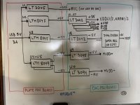
Exactly! That was very much my plan, based on some readings of Ott's book (an excellent recommendation from Mark) this morning (the part about ribbon cables). The latest block diagram is attached, and the mezzanine boards will be for the LTM8049.
Now, I'm learning more about EMI supression filters (especially the Murata ones), like the ones used on this DIYINHK board. And I need to learn about when to use these fancy WIMA film capacitors. Or when to use a 5,600μF or 6,800μF capacitor next to an LDO regulator. I could not get this capacity with a single SMD capacitor, but two or three mounted in parallel would do the trick.
But most importantly, I need to develop a better understanding of the schematics for the AKM evaluation board, because I think I made some errors in my power analysis. Once I have drawn some clean schematics for the entire board, things should get a lot more clear. And I'll be able to better separate supplies for digital lines from supplies for analog lines.
Attachments
Last edited:
- Home
- Source & Line
- Digital Line Level
- 8 × AK5578EN + 8 × AK4499EQ ADC/DAC Boards