Why is my evaluation board not yet up and running?
There have been several mentions of the fact that I should get my AKM evaluation board up and running, and that I should listen to it. So, why haven't I done that yet? For a very simple reason: if I make any mistake and I end up frying it, I will have to wait until November to get a replacement. And at $650 a pop, it's not the kind of mistake that I'd like to make too often. Therefore, until I feel confident enough to turn the power on, I'll keep staring at this silent board and its poor schematics, because that's the most that I can afford at this time.
Next month, I'm going to Tokyo for work, and I'll do everything I can to buy a couple of evaluation boards there. In fact, I am hopeful that I could meet some of its designers, maybe not during this trip, but during the next one (I'm usually in Tokyo once or twice a month). Equipped with these spares and some direct access to expert technical support, I should be able to bump my confidence level up.
I like to give myself crazy challenges, but I'm not a fool. A couple years ago, I got invited to an air safari in Namibia, flying what is best described as a moped with wings made of fabric. I took on the challenge, but only after a full week of training with a retired Boeing 747 pilot. It was painful, but it probably saved my life. On the second day of flying, one of the pilots who had not received this training crashed one of the three small planes we were flying. He and his passenger survived, but the latter killed himself a year later, flying a similar aircraft, for a commemoration flight made in honor of a friend of him who had killed himself in yet another similar aircraft a week earlier... Here are some pictures of the trip. Some of my very best memories...
Bottomline: we'll make this board sing, but only when the time is right.
Last edited:
I would say there is almost no situation where a 5600 or 6800 uF cap is needed before or after a regulator in a DAC or preamp. You are probably better off with much less. As far as film caps, they don't really belong in the power supply anymore with MLCCs being around. The only thing I would use them for is in active or passive filters in the signal path. Personally, I would use C0G surface mount ceramic before I used any film caps, but they are good in those positions.
You might not need a pre-regulator before the Jung regulator, it won't hurt, but you might be able to get away with passive filtering.
Those EMI filters can be good, it depends. There are LOTS of types, but they are predominantly some form of inductance, ferrite, or common mode choke + cap. You essentially just need to make sure you have sufficiently attenuated content that is outside the working bandwidth of the linear regulators (including Jung).
https://www.analog.com/media/en/technical-documentation/application-notes/an101f.pdf
I would say there is almost no situation where a 5600 or 6800 uF cap is needed before or after a regulator in a DAC or preamp. You are probably better off with much less. As far as film caps, they don't really belong in the power supply anymore with MLCCs being around. The only thing I would use them for is in active or passive filters in the signal path. Personally, I would use C0G surface mount ceramic before I used any film caps, but they are good in those positions.
You might not need a pre-regulator before the Jung regulator, it won't hurt, but you might be able to get away with passive filtering.
Those EMI filters can be good, it depends. There are LOTS of types, but they are predominantly some form of inductance, ferrite, or common mode choke + cap. You essentially just need to make sure you have sufficiently attenuated content that is outside the working bandwidth of the linear regulators (including Jung).
https://www.analog.com/media/en/technical-documentation/application-notes/an101f.pdf
Thanks a ton Chris, this is super helpful, and it will save me a lot of time.
A lot...
Thanks a ton Chris, this is super helpful, and it will save me a lot of time.
A lot...
No problem, I forgot to mention, watch out for huge caps on the output of circuits fed by the switchers. Some may not tolerate the inrush current. You might actually need a current limiter on the USB input. I think the USB spec itself only allows for 10 uF or something small like that.
One has to study the details to understand, and to the extent one is not at that level, maybe it would be wise to ask someone is is rather than jump to conclusions (something the human brain does automatically without being asked to by its owner, but those conclusions can be questioned by the brain's owner - please lookup dysrationalia and study kahneman when there is time).
Also, please see pics below for to understand about the suggested regulators.
Also, please see pics below for to understand about the suggested regulators.
Attachments
Last edited:
Thanks a ton Chris, this is super helpful, and it will save me a lot of time.
Chris knows his stuff alright, and I think he's a good guy. One place where he and some of us seem to disagree is that he doesn't think one can hear a difference between PCM and high sample rate DSD (IIUC). I am not aware that he ever tried with a good dac. In the end, I think an area where his knowledge may be lacking is in high end analog, not that he would necessarily agree. I think someone like Jam would probably agree, however.
On the other hand, I think you have heard a difference between PCM and high sample rate DSD. If so, then you probably don't believe you were hallucinating the perceived difference at the time.
Thus, film caps can have their uses in power supplies at times IMHO, and in the opinion of others you may be inclined to trust.
I hope Chris will forgive me for being so opinionated. Of late I have been trying to avoid public arguments with him.
Last edited:
Chris knows his stuff alright, and I think he's a good guy. One place where he and some of us seem to disagree is that he doesn't think one can hear a difference between PCM and high sample rate DSD (IIUC). I am not aware that he ever tried with a good dac. In the end, I think an area where his knowledge may be lacking is in high end analog, not that he would necessarily agree. I think someone like Jam would probably agree, however.
On the other hand, I think you have heard a difference between PCM and high sample rate DSD. If so, then you probably don't believe you were hallucinating the perceived difference at the time.
Thus, film caps can have their uses in power supplies at times IMHO, and in the opinion of others you may be inclined to trust.
I hope Chris will forgive me for being so opinionated. Of late I have been trying to avoid public arguments with him.
Yeah, I don't have any intentions into turning this thread into a battleground 🙂. I just wanted to point out that there are other ways, as you have.
One has to study the details to understand, and to the extent one is not at that level, maybe it would be wise to ask someone is is rather than jump to conclusions (something the human brain does automatically without being asked to by its owner, but those conclusions can be questioned by the brain's owner - please lookup dysrationalia and study kahneman when there is time).
Also, please see pics below for to understand about the suggested regulators.
Guilty as charged! I have a massive case of dysrationalia, and there is no cure for it. But this is why I am inclined to work on crazy projects like this one. They have no rational basis. They are unadulterated artistic endeavors with engineering pretense sprinkled on them just for good looks. What comes out of them in the end is anyone's guess. In that respect, I'm a freaking lunatic. And I am my own harshest critic. On that front, nobody will ever come close.
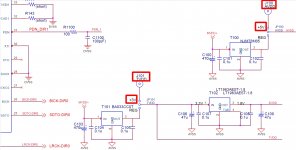
But I still do not understand what you are trying to communicate with these partial schematics taken out of context. A bit like 37mA with no justification. Why not 42mA while we're at it? I mean, that would work too, and it would give us a bit more headroom, and it's a much better looking magical number.
Yeah, I don't have any intentions into turning this thread into a battleground 🙂. I just wanted to point out that there are other ways, as you have.
And it would be really great if we didn't make things personal. We're all in this for the love of electronics and music, so let's keep it at that if possible.
Always be kind...
...I have a massive case of dysrationalia, and there is no cure for it.
Yet you are an instrument rated pilot? You know how to scan a 6-pack? You must be able to learn.
...I still do not understand what you are trying to communicate with these partial schematics taken out of context...
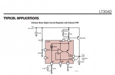
You said you didn't know which schematics to look at. The answer is those for the eval board, and in the LT3042 data sheet. Exactly the subject matter at hand.
Now you say you don't understand what the schematics mean in terms of being able to figure out how the recommended regulators could be proper to use with the dac? If so, why don't you take your best guess and let's hear it?
.. A bit like 37mA with no justification.
You know AK4499 data sheet is a pdf, right? And you know Acrobat reader has a search function, right? Didn't I already tell you its in the data sheet? Do I need to say the '37' you are looking for is the one that says 'ma' after it?
Look, the way you are going to get through this project, if you are going to, is to learn some things about engineering design. You learn by engaging your brain to do your homework whether its fun or not. The difficulty for many engineering students is that most of the fun for them doesn't start until they learn some things first. Part of the job for your project is to get used to finding the information you need. Part of it is starting to grok electronics more deeply than you do now. Its not just a bunch of simple rules that people can tell you as you need them. You need a whole bunch of them at once, so you have to start putting in paying your dues, there is no other way except to find someone else to do the work for you. Sad/cruel facts of life. Nothing personal. All the foregoing IMHO, of course.
Last edited:
ishizeno, great to see progress. Dysrationalia... that sounds like my country, Australia, after beer o'clock! 🙂
On a serious note, I haven't had time to get here but I have some quick suggestions and I'll try to catch up a bit tomorrow.
You can roughly divide audio designers, on the extremes as being objectively
driven, (measurements), subjectively driven (listening) and anywhere in
between.
I'm quite objectively AND subjectively driven. I'm always after good measurements, but I'm a firm believer that you have to listen, it's quite
surprising at times a) how the two don't necessarily correlate and b) what you can actually hear at times.
So without getting into any bun fight over this and in the spirit of forward
progress, I think a good strategy is to identify potential areas that are likely
to require tweaking with listening and allow flexibility to do this down the
track settling on best first guess for initial design.
For example, we all know the critical areas of DAC design, especially AK4499 are VREF supplies, bypassing, I-V design, I-V (analog) power supplies. So
you could make the VREF supplies on a small daughter board that tacks on to main DAC board with 3 connections, in / gnd /out (maybe 2 gnds). The first
board gets an LT3042/5 but down the track that can be changed with say an opamp / discrete hybrid design.
The I-V could also be on a small separate board which allows easy tweaking of opamps, caps, LPF corner freq etc etc. The same goes for bypassing.
Allow, within reason, some flexibility in component choice by using possible multiple pad option without compromising the overall design.
By doing this you can keep moving forward.
Doing careful listening tests takes a lot of time and you need a very good replay system. It can really bog a project down, especially something this
complex. If you can find ways to streamline that process or get someone else to help you, it's worth considering.
OK - there's my 2 cents - well, dollars.
cheers
Terry
Yet you are an instrument rated pilot? You know how to scan a 6-pack? You must be able to learn.
Actually, I do not. I am instrument rated, but I do not know how to scan a 6-pack. After the few lessons for my PPL, I moved to a Garmin G1000 glass cockpit. And for my IFR, I moved to the Avidyne avionics (a move I later regretted). Therefore, I used to know how to scan the Avidyne and the GNS430. I would never fly IFR with a 6-pack, because I've never been trained to scan it as an IFR pilot. It's a whole different scan method than on a glass cockpit. And I would not fly IFR on a G1000 either, because I'm not sufficiently proficient with it.
When I took my IFR check ride, the autopilot in my rented airplane was inoperable. I had to hand fly the whole 4 hours of checkride. Not an easy thing on a Cirrus SR22 with laminar airflow... Somehow, I managed to get my ticket though. That made me happy.
You said you didn't know which schematics to look at. The answer is those for the eval board, and in the LT3042 data sheet. Exactly the subject matter at hand.
I assumed that part, but these schematic do not help me understand why the designers of all these regulator boards felt the need to put very large capacitors there, and why I might not need them (per Chris' comment).
Now you say you don't understand what the schematics mean in terms of being able to figure out how the recommended regulators could be proper to use with the dac? If so, why don't you take your best guess and let's hear it?
What kind of game is that? If you know the answer to a question that was asked, why make it so hard to get to it? You might derive some pleasure from playing it that way, but I for sure don't. If you do not want to answer because you think I should RTFM, that's cool, just don't answer the question. I know I need to RTFM. But if RTFM is the answer to all my questions, then I should RTFM and come back in a few years to continue the project. But what fun would that be? I'm reading all the books I can, but these are not easy materials to get through, and if you don't mind, I'll keep asking my questions. My freedom is in asking the questions. Your freedom is in ignoring them.
You know AK4499 data sheet is a pdf, right? And you know Acrobat reader has a search function, right? Didn't I already tell you its in the data sheet? Do I need to say the '37' you are looking for is the one that says 'ma' after it?
Honestly, you're much nicer without the patronizing tone.
Of course I did that. But guess what? On Chrome running on my Windows 10 machine, the 019001308-E-00 datasheet for the AK4499EQ returns 24 results for the "37" search. And none of them relate to current. There are a few "37Hz" here, and a few "Table 37" there, but no "37mA" (that I could find, but maybe I need new prescriptions). Now, it might be that the PDF export for the document messed that one up and that only Acrobat Reader can find it. Or maybe I'll need to read the PostScript code directly in order to play archeology. Sure, I could do that...
Look, the way you are going to get through this project, if you are going to, is to learn some things about engineering design. You learn by engaging your brain to do your homework whether its fun or not. The difficulty for many engineering students is that most of the fun for them doesn't start until they learn some things first. Part of the job for your project is to get used to finding the information you need. Part of it is starting to grok electronics more deeply than you do now. Its not just a bunch of simple rules that people can tell you as you need them. You need a whole bunch of them at once, so you have to start putting in paying your dues, there is no other way except to find someone else to do the work for you. Sad/cruel facts of life. Nothing personal. All the foregoing IMHO, of course.
I get that part, and trust me, I'm paying my dues... And I'm doing it all in an open source fashion so that others don't have to pay the very same dues all the time. Knowledge is the one thing that only increases when shared. But I'd like to pay these dues to the gods of the trade, the ones in the heavens, not to any particular individual who decides which dues should be paid by which student. Unless you decide to be my sensei, but in that case, there are a lot of responsibilities that come with it, and I'm not sure that you want to take them on just quite yet.
For certain trades, I work with masters. For example, I am a student of tea ceremony. And everytime I go to Tokyo, I get a lesson from my sensei. And trust me, this stuff is all about paying your dues. It's hard stuff. But it's highly satisfying. But it's certainly not for everyone. It's a bit exotic. So exotic in fact that I even got National Geographic to write an article about it...
So you decide whether you want to be a friend or a sensei. I'm cool either way, but you can't be both at the same time.
Cheers!
Last edited:
Terry,
Great to read from you!
Best time of the day!
I'm in the same camp as you, with the only difference that I have zero education as a subjective listener. This will have to be learned the hard way.
I really like this approach...
This is an interesting idea: we could split the 2-unit DAC PSU board into two separate 1-unit PSU boards, one with all the LDOs, and one with the Jung/Didden Super Regulator used for VREF (with four AD825 OpAmps). This would allow us to tweak each board separately. I really like this idea actually...
We already considered this idea (putting the I-V OPA1612 OpAmps on the XLR board), but there was some fear that we might not be able to do that with the AK4499. It works for the Allo Katana, but it's using an ESS chip. The AK4499 has a totally different design that might make it impossible (Mark knows more about why that might be the case). But if we could make it work, that would be my preferred choice.
With our very tight space constraints, I fear that we won't be able to do much in this area...
Thank you so much Terry, this is really helpful feedback.
Cheers mate!
Ismael
Great to read from you!
ishizeno, great to see progress. Dysrationalia... that sounds like my country, Australia, after beer o'clock! 🙂
Best time of the day!
On a serious note, I haven't had time to get here but I have some quick suggestions and I'll try to catch up a bit tomorrow.
You can roughly divide audio designers, on the extremes as being objectively
driven, (measurements), subjectively driven (listening) and anywhere in
between.
I'm quite objectively AND subjectively driven. I'm always after good measurements, but I'm a firm believer that you have to listen, it's quite
surprising at times a) how the two don't necessarily correlate and b) what you can actually hear at times.
I'm in the same camp as you, with the only difference that I have zero education as a subjective listener. This will have to be learned the hard way.
So without getting into any bun fight over this and in the spirit of forward
progress, I think a good strategy is to identify potential areas that are likely
to require tweaking with listening and allow flexibility to do this down the
track settling on best first guess for initial design.
I really like this approach...
For example, we all know the critical areas of DAC design, especially AK4499 are VREF supplies, bypassing, I-V design, I-V (analog) power supplies. So
you could make the VREF supplies on a small daughter board that tacks on to main DAC board with 3 connections, in / gnd /out (maybe 2 gnds). The first
board gets an LT3042/5 but down the track that can be changed with say an opamp / discrete hybrid design.
This is an interesting idea: we could split the 2-unit DAC PSU board into two separate 1-unit PSU boards, one with all the LDOs, and one with the Jung/Didden Super Regulator used for VREF (with four AD825 OpAmps). This would allow us to tweak each board separately. I really like this idea actually...
The I-V could also be on a small separate board which allows easy tweaking of opamps, caps, LPF corner freq etc etc. The same goes for bypassing.
We already considered this idea (putting the I-V OPA1612 OpAmps on the XLR board), but there was some fear that we might not be able to do that with the AK4499. It works for the Allo Katana, but it's using an ESS chip. The AK4499 has a totally different design that might make it impossible (Mark knows more about why that might be the case). But if we could make it work, that would be my preferred choice.
Allow, within reason, some flexibility in component choice by using possible multiple pad option without compromising the overall design.
By doing this you can keep moving forward.
With our very tight space constraints, I fear that we won't be able to do much in this area...
That's one of the many reasons that I am doing this project with an open source model: I'd like experienced listeners who have their own reference setups to participate in the active evaluation of the design, every step of the way. And I am more than happy to provide free evaluation boards to anyone who is interested, trained, and equipped.Doing careful listening tests takes a lot of time and you need a very good replay system. It can really bog a project down, especially something this
complex. If you can find ways to streamline that process or get someone else to help you, it's worth considering.
OK - there's my 2 cents - well, dollars.
cheers
Terry
Thank you so much Terry, this is really helpful feedback.
Cheers mate!
Ismael
What kind of game is that? If you know the answer to a question that was asked, why make it so hard to get to it? You might derive some pleasure from playing it that way, but I for sure don't.
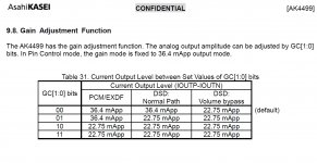
Two things, first an apology. Sorry for saying 37ma, that's how I remembered it. The actual number is 36.4ma as it turns out. Of course, I had to go through the data sheet searching for it since I didn't remember exactly where it was. Pic below.
Part of what may not have become evident yet is that one has to go searching through the data sheet at times. Who has to do it then, me? That's why I want you to start getting in the habit of doing it yourself, it is your project after all, but I am happy to help.
Changing the subject: I know it gets really complicated when you hear different advice from different people who do not always agree with each other, and who don't want to argue with each other in your thread. Some people will give you advice that will seem to be just what you needed, even if you find out later it didn't work in your project and you have no idea that's even what your problem is. Just another reason why this is a hard project for a beginner.
The other thing about the so-called 'game' is that people often may have some inchoate idea about something, but don't or cant easily pull it out and examine it. That is, people may guess right often enough showing they do indeed know something at some level, it just hasn't fully made its way into conscious awareness. In such cases they may say they don't know, but they may still guess right more often than chance would account for.
If you know some electronics or are starting to, you may at some level being starting to understand some things about capacitors, then again maybe not. One way to see is to take your best guess. If you need a some study material on caps, maybe we can find that for you.
Anyway, electrolytic caps are used to store more energy locally than ceramic caps can. They also may sound different from ceramic caps and from each other. That's because caps have different properties at different levels. Things like ESR and ESL are approximations, that's why they are 'lumped equivalents.' Large value ceramic caps are at some level piezoelectric. Electrolytic caps are like RC ladder networks, another but deeper approximation.
Anyway, eventually you may be able to miniaturize things using things like SMD ceramic caps and polymer electrolytics. But, you have to have a reference to listen to sooner than later, and it should start using known high end circuitry. If big caps sound good in a known way when you build a listening reference, then use them because they work and for no other reason.
When you want to compare what you can do with other components, then you have a reference you can trust for listening comparisons. Otherwise, there is no standard. THD won't tell you everything you need to know, nor will any other measurement or set of them an AP analyzer can do.
Changing the subject again:
Its easier to explain such things in person, and the amount of information is staggering at first. It will go in one ear and out the other unless one does homework to make it sink in.
Then there is that we still don't know each other very well and communicating back and forth in text is the worst possible way. Every misunderstanding that can occur will occur.
Attachments
Last edited:
The AK4499 has a totally different design that might make it impossible (Mark knows more about why that might be the case). But if we could make it work, that would be my preferred choice.
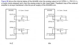
I/V opamp feedback loop routes through the dac chip. There is very high gain in the loop and it needs to be kept short. See pic below.
Attachments
Two things, first an apology. Sorry for saying 37ma, that's how I remembered it. The actual number is 36.4ma as it turns out. Of course, I had to go through the data sheet searching for it since I didn't remember exactly where it was. Pic below.
Part of what may not have become evident yet is that one has to go searching through the data sheet at times. Who has to do it then, me? That's why I want you to start getting in the habit of doing it yourself, it is your project after all, but I am happy to help.
Changing the subject: I know it gets really complicated when you hear different advice from different people who do not always agree with each other, and who don't want to argue with each other in your thread. Some people will give you advice that will seem to be just what you needed, even if you find out later it didn't work in your project and you have no idea that's even what your problem is. Just another reason why this is a hard project for a beginner.
The other thing about the so-called 'game' is that people often may have some inchoate idea about something, but don't or cant easily pull it out and examine it. That is, people may guess right often enough showing they do indeed know something at some level, it just hasn't fully made its way into conscious awareness. In such cases they may say they don't know, but they may still guess right more often than chance would account for.
If you know some electronics or are starting to, you may at some level being starting to understand some things about capacitors, then again maybe not. One way to see is to take your best guess. If you need a some study material on caps, maybe we can find that for you.
Anyway, electrolytic caps are used to store more energy locally than ceramic caps can. They also may sound different from ceramic caps and from each other. That's because caps have different properties at different levels. Things like ESR and ESL are approximations, that's why they are 'lumped equivalents.' Large value ceramic caps are at some level piezoelectric. Electrolytic caps are like RC ladder networks, another but deeper approximation.
Anyway, eventually you may be able to miniaturize things using things like SMD ceramic caps and polymer electrolytics. But, you have to have a reference to listen to sooner than later, and it should start using known high end circuitry. If big caps sound good in a known way when you build a listening reference, then use them because they work and for no other reason.
When you want to compare what you can do with other components, then you have a reference you can trust for listening comparisons. Otherwise, there is no standard. THD won't tell you everything you need to know, nor will any other measurement or set of them an AP analyzer can do.
Changing the subject again:
Its easier to explain such things in person, and the amount of information is staggering at first. It will go in one ear and out the other unless one does homework to make it sink in.
Then there is that we still don't know each other very well and communicating back and forth in text is the worst possible way. Every misunderstanding that can occur will occur.
Apology accepted my friend. We're all good.
And I agree with everything you wrote. Very helpful.
Clearly, we're looking at a very challenging project, and it will be challenging for all involved, in different ways. This is another thing that makes it so interesting to me. It's as much an engineering challenge as it is a social one.
Cheers!
Ismael
I/V opamp feedback loop routes through the dac chip. There is very high gain in the loop and it needs to be kept short. See pic below.
That makes sense. Probably best kept on the same board, as you already indicated.
And I am of the opinion that we should stick to the high-level layout of the AKM evaluation board as much as possible. So, until further notice, the I-V stage is on the same board as the DAC chip.
Who wants a free evaluation kit?
So far, the OTO™ system has been designed to fulfill my own personal needs, but I'm sure that other people would love to get a DIY portable DAC powered by the best converter in the world. And it would be great to get some input from these folks, as early in the process as possible.
Therefore, I am more than happy to fund the first batch of 12 kits. They will be made of:
1. The DAC PSU Board.
2. The Plate PSU Board.
3. The DAC Board.
4. The XLR Board.
5. The Plate MCU Board.
6. The Brick Enclosure.
7. The Plate Enclosure.
These components will be released in an incremental manner, probably in the order outlined above. Somewhere along the way, a Development Board will be added as well. This board will allow one to plug some of the boards listed above and will provide standard 0.1" headers to make it easier to connect the boards to various power supplies, audio components, and measuring equipment.
I will ship the components to you as they become available, anywhere in the world, for free. You can even use a P.O. box if you'd rather remain anonymous.
Once complete, this kit should work as a battery-powered portable DAC (the Plate MCU Board will include an STM32H743 with a properly licensed Thesycon U-HEAR firmware). You'll have to add your own preamp though, but we'll work on that brick as soon as we're done with the DAC brick and the AK5578EN-powered brick.
The deal is pretty simple:
1. You make a post on this thread explaining why you should get a free kit.
2. If I think you should get a kit, you get added to the list. First added, first served. No more than 12.
3. You provide as much constructive input to the thread as possible.
4. You do so as kindly as your personal character will allow.
5. You play with whatever you get and provide as much constructive feedback as possible.
6. You keep the kit if you like it, or you gift it to someone who could learn something useful from it.
Once we have something that we're all proud of, we try to meet in person, In Japan, and go show off our creation to the designers at AKM. If you really can't afford the trip there, I'll help with miles on United Airlines and/or nights with Hyatt.
All I'm asking in return is K2: Knowledge and Kindness.
I hope you enjoy the ride as much as I do.
Ismael, aka ISHI (this means "stone" in Japanese, ishizeno is an old alias that I do not really use anymore).
PS: If you have friends who you think would be good contributors, please point them our way...
Last edited:
First of a three part series on bypass caps: https://www.edn.com/design/analog/4...gulator-and-its-output-capacitor-can-interact
A different topic, but also worth reading: https://www.edn.com/design/analog/4...t-2--Design-to-minimize-signal-path-crosstalk
A different topic, but also worth reading: https://www.edn.com/design/analog/4...t-2--Design-to-minimize-signal-path-crosstalk
First of a three part series on bypass caps: https://www.edn.com/design/analog/4...gulator-and-its-output-capacitor-can-interact
A different topic, but also worth reading: https://www.edn.com/design/analog/4...t-2--Design-to-minimize-signal-path-crosstalk
Thanks! Super useful.
- Home
- Source & Line
- Digital Line Level
- 8 × AK5578EN + 8 × AK4499EQ ADC/DAC Boards