So I'm right, of all the tests you did, what you like the most is the triode mode in this type of valves?
mrpunkk,
You are correct.
When there is no global negative feedback, and no schade negative feedback, and no feedback that is around two stages.
(only local negative feedback in a stage).
But let me list some of the reasons I like Triode wired:
(Triode wired disadvantages first)
Less power out
Less gain
(Non Triode wired disadvantages) . . .
More distortion without negative feedback
Lower damping factor without negative feedback
More complex
Usually needs some negative feedback around at least 2 stages, may need global negative feedback.
More likely to be unstable, because has to have 2-stage or global negative feedback
(Triode wired advantages next)
Highest damping factor
Lowest distortion
Simplest design
Most stable
I usually do not need very much power.
I usually do not need very much gain.
That takes care of the Triode wired's disadvantages.
The above criteria generally apply to my designs of my single ended amplifiers, my self inverting amplifiers, my push pull amplifiers, and my balanced amplifiers.
I think I have honed-in on sound that I like for my listening situations, often near-field, and my many different models of loudspeakers.
Your sound preferences, power needs, etc. may differ.
Last edited:

I still try the simulations with ltspice and in the real world, and compare.
One thing I noticed is that when I increase the value of the common cathode resistor of the 12ax7, the THD decreases, obviously losing gain.
What is the explanation?
Does it make sense to raise the resistance to 500ohm to lower the thd? Or am I making the 12ax7 work poorly?
And another thing I noticed is that the anodes of the 12ax7 have a difference of 1 or more volts DC between themselves, which is then seen in a difference in AC before reaching the 6v6 grid, shouldn't they have the same amplitude? I measured this on my amplifier in the real world and the same thing happens.
I am using the schematic that is posted here to test LTspice
These are all questions that come to me but I don't have anyone around to answer them, I hope you can help me.
Attachments
You are using a Paraphase splitter.
The 12AX7 100k plate loads are equal.
The 270k Rg resistors of the 6V6 g1 grids are equal.
You want the 12AX7 plate voltages to be equal in amplitude, but of opposite phase.
You got the phase right. But . . .
With equal amplitude voltages in opposite phase across the [equal] 270k resistors, that would cause the junction of two 270k resistors to be 0.0V signal, Zero volts signal.
With 0.0V signal driving the 2nd grid of the 12AX7, its plate would not have any output.
Instead, it causes the un-balanced voltage of the phase splitter plates, and that is what drives the 12AX7's 2nd grid.
Slightly increase the value of R12, 270k resistor appropriately. Try 300k for a start.
See if that brings the two amplitudes to be equal.
Or let the amplifier's global negative feedback take care of most of the 2nd harmonic distortion that is caused by the paraphase inverter.
Well, you changed the circuit, Post # 43, there is no global negative feedback. Not to worry, that is OK. Back to changing R12 as above.
OR,
Change the phase invertor circuit to use the intrinsically balanced amplitudes of a CCS and cathode coupled phase inverter (trading off the lower gain it has [about 1/2], versus a paraphase inverter).
Enough gain? Well, there is no global negative that reduces gain.
With a 12AX7 and CCS, you will either need a negative voltage to run the bottom of the CCS;
Or a couple of 3V batteries, with the battery - terminal connected to the grid stopper resistor, and the + terminal connected to the 270K resistor and coupling cap.
This is series battery bias, the best kind for battery life (the same as the shelf life as the battery).
Have fun!
Last edited:
Hi @6A3sUMMER ,With equal amplitude voltages in opposite phase across the [equal] 270k resistors, that would cause the junction of two 270k resistors to be 0.0V signal, Zero volts signal.
there's signal on the second grid of the phase splitter, because the cathodes of the phase splitter aren't connected together.
R9 and R10 create the unbalance that make it a phase splitter.
Zintolo,
Which schematic?
Post # 43?
12AX7:
One plate drives a coupling cap, to a 270k in phase.
The other plate drives a coupling cap, to a 270k in the opposite phase (out-of-phase).
The two 270k resistors are in series (with a junction in the middle).
Suppose that the in-phase signal peaks at +10V on the 270k resistor.
If the out-of-phase signal peaks at - 10V on its 270k resistor, guess what happens . . .
We get a cancellation of the voltage at the junction of the two 270k resistors (no signal voltage to the right 12AX7 grid).
But reality sets in, because the two plate voltage swings are Not equal amplitude swing, so we Do get a signal voltage to the right 12AX7 grid.
We need to change the bottom 270k resistor to perhaps 300k or 330k, so that the two plate voltage swings are equal amplitude.
Another way to look at it . . . the two 270k resistors are a voltage divider. We need some signal to go to the grid of the right 12AX7 grid.
With the two phases, and equal voltages, we need the divider to provide some signal voltage at the right 12AX7 grid, so we need an unequal divider to do that.
I hope that explains it to you.
Yes, please look better this point: impedance to ground of the two cathodes is different, therefore the gain of the two sides is different.Zintolo, Which schematic? Post # 43?
This is the other key point of this circuit: the reason why the two 270k are not directly grounded like in all others biasing circuits is that R9 is part of the voltage divider and where, together with R10, we get the two phases.The other plate drives a coupling cap, to a 270k in the opposite phase (out-of-phase).
The two 270k resistors are in series (with a junction in the middle).
You are looking at that circuit thinking it's a standard paraphase, but it's not. Look at it again!Suppose that the in-phase signal peaks at +10V on the 270k resistor.
If the out-of-phase signal peaks at - 10V on its 270k resistor, guess what happens . . .
Not exactly. What you say happens in a standard biasing circuit where the grid leak resistors are tied together to a low impedance voltage reference.Another way to look at it . . . the two 270k resistors are a voltage divider.
Here R9 comes in as a voltage divider to send to the grid of the second triode a signal that is the difference of the two plates (difference due to R10), scaled down by the voltage divider composed by the two 270k resistors and R9.
We need an equal voltage divider, because we created the difference with a different cathode impedance to ground in the two triodes of the phase inverter.With the two phases, and equal voltages, we need the divider to provide some signal voltage at the right 12AX7 grid, so we need an unequal divider to do that.
Ditto. 😉I hope that explains it to you.
Zintolo and mrpunkk,
Zintolo,
Change R9 from 47k to 5.6k, and rewire that part of the circuit?
That is not the same at all, not the same circuit.
mrpunkk,
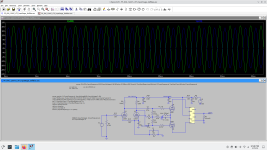
Post # 43 spice does not tell me which 12AX7 plate is the larger amplitude Green sine wave, and which 12AX7 plate is the smaller amplitude Blue sine wave.
Please tell me which 12AX7 plate has the larger Green amplitude sine wave?
Both of you,
I need to know which plate is 'Green', and which plate is 'Blue', before I do any more long hand analysis of the circuit versus spice.
I do not use spice.
Food for thought: Think of a paraphase inverter as a 'servo system' with a divider to provide feedback.
If the divider of plate 1 and plate 2 divides it equally, the 'servo system' has Zero error, No feedback signal.
With no feedback signal, the grid on the right does not have any signal, and would not have any plate output signal.
This reminds me of the US Naval Frigate's gyro repeaters that I worked on . . . they stopped turning when the error signal became zero. Same thing.
Thanks!
Zintolo,
Change R9 from 47k to 5.6k, and rewire that part of the circuit?
That is not the same at all, not the same circuit.
mrpunkk,
Post # 43 spice does not tell me which 12AX7 plate is the larger amplitude Green sine wave, and which 12AX7 plate is the smaller amplitude Blue sine wave.
Please tell me which 12AX7 plate has the larger Green amplitude sine wave?
Both of you,
I need to know which plate is 'Green', and which plate is 'Blue', before I do any more long hand analysis of the circuit versus spice.
I do not use spice.
Food for thought: Think of a paraphase inverter as a 'servo system' with a divider to provide feedback.
If the divider of plate 1 and plate 2 divides it equally, the 'servo system' has Zero error, No feedback signal.
With no feedback signal, the grid on the right does not have any signal, and would not have any plate output signal.
This reminds me of the US Naval Frigate's gyro repeaters that I worked on . . . they stopped turning when the error signal became zero. Same thing.
Thanks!
Last edited:
is the left part of the 12ax7 in the schematicPlease tell me which 12AX7 plate has the larger Green amplitude sine wave?
I did what you suggested and it turned out even, now I have to test it on the real amplifier.@mrpunkk Try this mod, now you can play with R9 to make the driving signals for the 6V6's. The original schematic relies on global negative feedback. If you remove it, then you need to make everything as linear as possible.
What good and bad things does this solution have? I think the thd went up.
Where did you get this solution from?
mrpunkk,
Thanks.
The left 12AX7 triode cathode sees 100 Ohms through a 100uF cap to ground.
That, and the 100k plate load resistor in parallel with 270k Rg sets its gain at mid frequencies.
The right 12AX7 triode cathode sees 100uF cap to ground.
That, and the 100k plate load resistor in parallel with 270k Rg sets its gain at mid frequencies.
It's gain should be Very slightly higher than the left 12AX7 triode.
But, as I already said, the 270k 270k divider sends too little signal to the right 12AX7 grid, causing the lower Blue voltage.
The problem of the original circuit was there, because the 270k 270k divider does not provide enough signal voltage to the right 12AX7 triode's grid.
If you would try changing the bottom 270k resistor (R12) to a higher value (300k, 330k), that will tend to fix the problem.
When you do that, do not change the original value of R9, and do not change the wiring diagram from the original.
The plate signal amplitudes would be more equal.
*** That should be an easy thing to test in spice.
I expect at the same output power as before the new increased value for the 270k resistor, the THD will not go up.
Instead, you changed the circuit resistor connections, and changed the value of R9, as jcalvarez suggested, Right?
Aha, the THD went up. Well, that is probably due to the 'fix' method you used.
Have Fun!
From nowhere, but probably it has been done many times.Where did you get this solution from?
I'd really change the approach, and use a simple concertina inverter and a voltage amplification stage. Simpler and more predictable circuit. You will loose gain, but there should be enough left to drive the 6V6
zintolo,
AC signal gain . . .
Left triode cathode is 100 Ohms + 100uF away from ground.
Right triode cathode is 100uF away from ground.
The higher impedance at the left triode that includes 100 Ohms causes lower gain, versus the right triode cathode that is has lower impedance to ground, the right triode actually has more gain.
Just the opposite of the plate signal amplitudes, which is caused by the incorrect signal division of R11 and R12.
Equal plate amplitudes that are divided equally, = no signal from the divider.
Whereas, Un-equal amplitudes that are divided equally = signal from the divider, exactly what is happening.
So, to ge equal amplitudes, we need the division to be un-equal, in order for there to be a signal to the right triode grid.
By the way, the original circuit with the 270k Rg, and the grid stopper, and the 47k, are all at OVDC. There is no output tubes grid bias, all bias is according to the cathode voltage, R16 the common self bias resistor, which is higher than the 0VDC at the grids.
Each 6V6 grid is 1k + 270k + 47k in series to Ground (OVDC).
These are not obvious to many, including me, when I first tripped up on it.
Last edited:
your solution 6A3sUMMERIf you would try changing the bottom 270k resistor (R12) to a higher value (300k, 330k), that will tend to fix the problem.
When you do that, do not change the original value of R9, and do not change the wiring diagram from the original.
The plate signal amplitudes would be more equal.
*** That should be an easy thing to test in spice.
Is it a problem with the original design?
With this solution will I notice better sound?
I think this design has the target to use cheap trafos thanks to the PP configuration and low Z drive of the 6V6 in triode configuration, plus single-ended-like even harmonics due to the limping phase inverter.
R9 can be substitued with a 100k linear potentiometer (connected like a reostat) in series with a 4k7 resistor to select on the fly the amount of even harmonics you want: they will become independent from the volume you are listening at.
R9 can be substitued with a 100k linear potentiometer (connected like a reostat) in series with a 4k7 resistor to select on the fly the amount of even harmonics you want: they will become independent from the volume you are listening at.
mrpunkk,
Well, it looks like changing the bottom 270k to 300k brought the signal amplitudes of the two plates closer to equal.
And if it were me, I would remove the 100 Ohm resistor from the left cathode, and connect the left cathode directly to the right cathode.
I bet that would be even better.
That should be an easy thing for those of you that use spice.
You said:
"Is it a problem with the original design?
With this solution will I notice better sound?"
I do not know the designer's intent.
Perhaps he wanted some 2nd harmonic distortion from one plate of the phase splitter circuit; perhaps not. But . . .
The schematic is inspired by several other 6V6 schematics, and then modified, perhaps by more than one designer.
I instantly recognized the Dyna circuit (perhaps the inspiration/origin of this schematic, and that there were some modifications, there is even a common mistake of those who interpret the original Dyna input circuit and improperly modify it.
Which sounds better, a little 2nd harmonic and 2nd Order intermodulation distortion, or less of both of those. _ You decide _.
Only your ears can tell you.
And your speakers can influence that (speakers have 2nd harmonic distortion, that partially cancels, or partially aids, the 2nd harmonic distortion of the amplifier).
Just swap the two speaker cable leads on the amplifier's Black and Red outputs. One way increases, the other connection direction reduces the distortion .
The amplifier can use inexpensive push pull transformers, but will get to a higher level performance with higher quality output transformers.
I would be surprised if you are not pleased with the sound in any case.
And not all $5000 amplifiers sound good (or some listeners do not hear what they would like to hear).
It often comes to preferences, and how the system works as a whole (such as the amplifier and speaker creates either positive synergy, or creates negative synergy).
The 6V6 connections do not show whether they are in Triode wired mode; Ultra Linear mode; or Beam Power mode.
I forgot what you said in your posts, but I am guessing that because you are not using global negative feedback the 6V6 tubes are in Triode Wired mode.
Hi @6A3sUMMER , they are connected in triode.The 6V6 connections do not show whether they are in Triode wired mode; Ultra Linear mode; or Beam Power mode.
In LTSPICE there are models specificaly written for non-triode tubes connected in triode, and as a standard they have the suffix "T" and uses the triode symbol.
It would be then interesting, considering the 2nd harmonic behaviour of this PP amp, to implement what Keibert proposed in 1954 to reduce 3rd harmonic ( https://www.one-electron.com/Archiv...System Design Factors for Audio Ampifiers.pdf ) by adding a 1/gm resistor from cathode of the output tubes to ground.
https://www.diyaudio.com/community/threads/ltp-and-h3-distortion.283787/post-4546788
It would then be a mixed-bias amp.
https://www.diyaudio.com/community/threads/ltp-and-h3-distortion.283787/post-4546788
It would then be a mixed-bias amp.
- Home
- Amplifiers
- Tubes / Valves
- 6V6 with and without FB (LTspice)