Diabolical Artificer,
I enjoy old and new recordings:
Some in concert halls; some outdoors; some in studios; some in padded "telephone booths" recorded one track at a time over a few days or weeks;
and you name the other methods.
individual [close] microphones often give clearer sound of instruments, that is way different than being 100 feet away with the high frequencies rolled off more than the low frequencies (attenuation due to air molecule acceleration).
The low frequency Horn of the Queen Mary could be detected by instruments 100 Miles away!
1. Take your favorite amplifier. Listen with the speaker connected directly to the output.
2. Then connect a resistor in series from the amp + Tap that is equal to the speaker's rated impedance (8 Ohm resistor from an 8 Ohm + Tap, to the speaker + terminal). Turn the volume up very slightly, in an attempt to compensate the loss in the resistor.
Listen again, You either will, or will not, hear a difference.
3. Put a single pole switch across the 8 Ohm resistor, and do quick AB testing, keeping in mind the power loss of the resistor.
Have Fun!
Your mileage may vary.
jcalvarez,
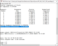
what if I want to compare it with 6v6 in ul mode? What subctk and model can I use?(i use ayumi also) I tried some but they gave me ridiculous output power or THD values.
what if I want to compare it with 6v6 in ul mode? What subctk and model can I use?(i use ayumi also) I tried some but they gave me ridiculous output power or THD values.
1. Are we actually building amplifiers in this thread and testing them, or at least listening to them?
Or,
Are we Mostly just simulating amplifiers in this thread; not building, and not listening? (22 Posts already).
2. Generalization:
The more negative feedback; local, global, nested, etc., that we can apply without oscillation, etc. . . . the more the amplifiers will sound the same.
Just my opinion.
I often tell others that tube rolling with the same type of tube number, but different manufacturers, surprise . . . the difference in sound is minimum when the amplifier uses lots of negative feedback.
Have fun designing, building, . . . and Listening!
Last edited:

For UL I just used the Ayumi 6V6 tetrode model, that's it. THD is not brilliant, but reasonable. Again, this is just a simulation.jcalvarez,
what if I want to compare it with 6v6 in ul mode? What subctk and model can I use?(i use ayumi also) I tried some but they gave me ridiculous output power or THD values.
Attachments
Interesting.
You used a Tetrode model.
You make me remember the 4-65A se amplifier I built.
Now there is a tetrode!
You used a Tetrode model.
You make me remember the 4-65A se amplifier I built.
Now there is a tetrode!
Yup. There is no (that I know of!) beam power tetrode model. All Ayumi models use tetrode to model pentodes and beam power tetrodes. Some other models are created directly from datasheet curves. So far the models are relatively accurate, especially for common tubes like 6L6/6V6 and the likes. Having said that, as usual, there is plenty of room for improvement.Interesting.
You used a Tetrode model.
You make me remember the 4-65A se amplifier I built.
Now there is a tetrode!
jcalvarez,
I am not talking about the likes of KT66, 6L6, EL34 tubes. They have beam formers, beam formers, and suppressor grids respectively.
The 4-65A Beam Power Tetrode has only 4 elements (four elements):
Filament
Control Grid
Screen Grid
Plate
The 4-65A control grid and the screen grid are both Bird Cage grids.
They have the same number of vertical wires, and they are very carefully lined up to each other.
(the openings between the wires line up, so the filament "sees" the plate directly in the lined-up spacing between the control grid wires and screen grid wires.
That is a TRUE Beam Power Tetrode.
What is in a name?
Nobody seems to care anymore, the historical names have been abused and perverted.
Just an old codgers historical opinion.
@6A3sUMMER I understand the difference between pure tetrodes and pentodes/beam power tubes. I mentioned 6L6 because it is a well known tube, with good models from simulation. I do not have your phenomenal experience and encyclopedia-like knowledge of electronics, always enjoy reading your posts here, they are very informative.
I never had or saw a real tetrode in my life, not a lot of options growing up in Cuba (old radio and TV tubes) , and then only reconnecting with my youth-hobby 3 years ago. I do have now a couple of GU-72 tetrodes, planning to do something with them.
I never had or saw a real tetrode in my life, not a lot of options growing up in Cuba (old radio and TV tubes) , and then only reconnecting with my youth-hobby 3 years ago. I do have now a couple of GU-72 tetrodes, planning to do something with them.
I already built the amplifier, and I like how it sounds without UL and in triode mode. but I wanted to see what the differences are in the simulation, in the absence of an oscilloscope it is the only thing I have left.1. Are we actually building amplifiers in this thread and testing them, or at least listening to them?
Or,
Are we Mostly just simulating amplifiers in this thread; not building, and not listening? (22 Posts already).
2. Generalization:
The more negative feedback; local, global, nested, etc., that we can apply without oscillation, etc. . . . the more the amplifiers will sound the same.
Just my opinion.
I often tell others that tube rolling with the same type of tube number, but different manufacturers, surprise . . . the difference in sound is minimum when the amplifier uses lots of negative feedback.
Have fun designing, building, . . . and Listening!
6A3sUMMER I realized that what you like most is the triode mode of the 6v6, or better in SE format? That's going to be my next project.
Do you say that by changing the output valves, the sound changes more without some type of FB?
Interesting, it doesn't work for me by switching to tetrode and using Ayumi's 6v6, strange isn't it?

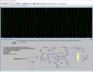
1. Your schematic has an error.
The output of the parallel RC network C3 R7, from the output transformer secondary is shorted to ground by the 100uF cap, C7.
So, there is no negative feedback.
Either C7 belongs on the other 12AX7 cathode to ground,
Or
C3 R7 needs to connect to the other 12AX7 to ground. **
One of the above will result in Positive feedback, I think that is **, but that depends on how the output tube screens and plates are connected to the output transformer windings; and how the secondary connections are properly or improperly phased.
Check the schematic in Post # 24. The global negative feedback connection seems to be correct.
Once you fix that, you may see a difference in the results of the simulation (this time with, and without global negative feedback, when you connect C3 R7, and when you disconnect C3 and R7).
2. I would never be able to do what I do without an oscilloscope . . .
and a few other basic test equipments:
DMM,
Function generator for fast rise square waves,
Denon Audio Test CD for different frequencies sine waves, 2nd order intermodulation dual tones, 3rd order intermodulation dual tones, and a single clock time Impulse.
I am thankful that I do not have to resort to simulation software.
Last edited:
I corrected the error but it still doesn't work, I'm making something else wrong.
I already understood that everything would be better with the right equipment, for now I don't have it, I can only play with the simulations and listening
I already understood that everything would be better with the right equipment, for now I don't have it, I can only play with the simulations and listening
Send me your .asc file, I'll check.I corrected the error but it still doesn't work, I'm making something else wrong.
Good catch. I looked at the screenshot, but missed that.Thanks, but I found the error, I was placing the bottom 6v6 valve backwards, reversing the grids.
Thanks anyway, now I can play a little, even though I don't have an oscilloscope.
I hope to have one soon
About oscilloscope: REW software (free), a decent sound card and an 8ohm 25/50W resistor can be used to check the output signal, with an appropriated voltage divider in order to not fry the sound card. It will also allow you to see the harmonic profile of the real thing, and act as a geterator for simple test signals.
About oscilloscope: REW software (free), a decent sound card and an 8ohm 25/50W resistor can be used to check the output signal, with an appropriated voltage divider in order to not fry the sound card. It will also allow you to see the harmonic profile of the real thing, and act as a geterator for simple test signals.
Do you have more information about that?
Good info here: https://www.diyaudio.com/community/threads/how-to-distortion-measurements-with-rew.338511/
The REW home page: https://www.roomeqwizard.com/
Always remember, it can't measure DC, and always have to use voltage dividers to protect the sound card input.
The REW home page: https://www.roomeqwizard.com/
Always remember, it can't measure DC, and always have to use voltage dividers to protect the sound card input.
mrpunkk,
I forgot to answer your question from Post # 29:
"Do you say that by changing the output valves, the sound changes more without some type of FB?"
Generally:
The more negative feedback there is in a loop which includes a tube that you are tube rolling . . .
The less likely you will be able to hear differences between various manufacturers, vintages, etc.
If a tube is Not included in a negative feedback loop, global or local . . .
Then if there are any sound differences between various manufacturers, vintages, etc., the easier it will be to hear those differences
(versus hearing any differences with lots of negative feedback).
Generally:
For local negative feedback that includes a tube . . .
The highest to lowest amounts of local negative feedback are:
1. Triode Wired pentodes and Triode Wired beam power; and Unity Coupled plate cathode such as McIntosh.
2. Ultra linear (such as 20% to 50%).
3. Cathode feedback (as often practiced from the output transformers speaker taps; as opposed to using large impedance dedicated cathode taps, which is closer to Unity Coupled).
Simple explanation:
Pentodes and beam power tubes in their "Native" mode can be viewed as if the screen is connected to 0% Ultra Linear Taps.
Triode Wired pentodes and Triode Wired beam power tubes can be viewed as if the screen is connected to 100% Ultra Linear Taps.
True Ultra Linear is somewhere in between those two extremes (>>0%; <<100%).
I have designed and built single ended amplifiers with beam power tubes in Ultra Linear using 50% and 80% UL taps.
In my opinion, if you use a 80% UL tap, then instead you might as well Triode Wire the tube.
Last edited:
- Home
- Amplifiers
- Tubes / Valves
- 6V6 with and without FB (LTspice)