
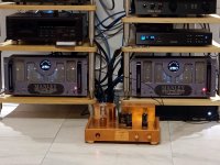
Didn't get as much done as expected yesterday (daddy duty) but here's a quick shot of the advanced test setup, spy those home made purpleheart knobs on the rotary switches and volume knob-

The little SMPS power unit is handy for quick adjustments and will hold me over until I get more of a test PSU together. Its quiet enough without additional filtering.
I ordered a USB setup to do some basic testing also. Behringer UCA222. Cheap but a start.
The little SMPS power unit is handy for quick adjustments and will hold me over until I get more of a test PSU together. Its quiet enough without additional filtering.
I ordered a USB setup to do some basic testing also. Behringer UCA222. Cheap but a start.
Nice man!
And here's the best part! That DC-DC boost is the noisiest piece of crap I've ever used. So if you got it "quiet" enough, imagine if you used this! And it's isolated, too! I use it to generate the negative bias voltage in all of my amps. And to make the power for my preamp (using the 200VAC output and a Delon into my Simple TL783 Regulator).

Here is a shot of the PSU I use for the preamp (This pic doesn't show the wiring finished yet though).
The outputs to the preamp through three cables are 12V for heaters, 340V for line/HP amp, 340V for phono, 280V for buffers, 12AU7/6E2 level meter, and gain for EQ loop, and finally 5V for the analog to TOSLink output.

Here's the preamp it powers. Again the wiring isn't finished in this shot.

And here's the best part! That DC-DC boost is the noisiest piece of crap I've ever used. So if you got it "quiet" enough, imagine if you used this! And it's isolated, too! I use it to generate the negative bias voltage in all of my amps. And to make the power for my preamp (using the 200VAC output and a Delon into my Simple TL783 Regulator).
Here is a shot of the PSU I use for the preamp (This pic doesn't show the wiring finished yet though).
The outputs to the preamp through three cables are 12V for heaters, 340V for line/HP amp, 340V for phono, 280V for buffers, 12AU7/6E2 level meter, and gain for EQ loop, and finally 5V for the analog to TOSLink output.
Here's the preamp it powers. Again the wiring isn't finished in this shot.
Last edited:
Hi Salas,
Back in post #3723 you mentioned about how to use a bit of NFB. Would your formula of resistors work if instead a 100K input pot I had this input transformer installed? I've since swapped a few things around, and am using a balanced dac, hence the input transformer.
https://cinemag.biz/line_input/PDF/CMLI-15-15B.pdf
I have a 12K resistor across the secondary.
I'm unclear on how the input transformer affects all the calculations.
I have the 100K pot now on the output of the preamp FYI, but I don't think that matters.
Thanks!
"
I wonder, would 7.5dB gain be enough for you? In other words two and a half times lower than you now got. That change can be implemented with a negative feedback network. Add 120K in series between the input (after the pot) and the 1K grid stopper. From their node connect a 560K resistor to the stage's output (after the output capacitor). Microphony will go down, noise will go down, THD will go down. Easy to do, evaluate and decide.
Don't use a higher than 50K volume pot with this arrangement. Matter of the pot's output impedance interfacing. Otherwise let me know to give you alternative values if you use a 100K pot or in case you want a different gain.
"
It should work with the input transformer too. Since the Tx has low enough output impedance you can use 47K and 220K instead for more bandwidth.
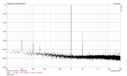
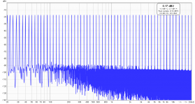
Here's an example of 10dB gain (3.2X) and 6dB NFB I recently modified. Enough for a phono source.
Not excessive with normal sensitivity amps on other sources. Tests nicely on FFT and sounds terrific.
Not excessive with normal sensitivity amps on other sources. Tests nicely on FFT and sounds terrific.
Attachments
Thanks Salas. I’m interested in experimenting with NFB these days. I’m also building a DHT preamp at the moment.
When you bring it up though, some people are very much opposed. Not sure why it’s so polarizing lol
Will try and listen for myself.
Also, I know if the open loop gain was infinite, the gain becomes Rf/Ri, correct? but since open loop here is not infinite, what’s the math to calculate the actual final gain? I read valve wizards pretty thorough evaluation but it’s a bit complicated description. Will have to read a few more times. Do you have a short cut thumbnail napkin sketch ballpark calculation method?
Last edited:
...And if the output impedance was zero. There's no good shortcut calculation I am afraid. Hands on would be use 1Meg rheostat as variable Rf and measure the gain results in a specific circuit.
I see. Ok that’s an answer too. Thanks!...And if the output impedance was zero. There's no good shortcut calculation I am afraid. Hands on would be use 1Meg rheostat as variable Rf and measure the gain results in a specific circuit.
Well at this point I am pretty much hands on which is a good way to learn. I’ll try to lean longhand too with some more reading. Then maybe spice down the road as things progress.
I linked my #4,166 shunt NFB 6V6 preamp version in post #1. Some would also call such an NFB scheme "Schade". Worth linking I think because it is a valid gain moderation example. Built and tested.
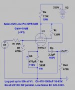
Salas was the best configuration for small gain, I want to use to amplify the noDac to a 2Vrms that is the standard outpout of DACs?
As attached schematic?Its easy, make #4,166 but with Ri 63k Rf 560k for gain 3.58 (0.56VRMS*3.58=2VRMS).
Attachments
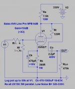
Will work very near to the original. Expect about 23mA Ia, 145V across the tube, and 12.6dB gain (15.5dB when R5 is bypassed with a cathode cap). Cin 0.22u is not needed. R13 will dissipate 3W, thus >5W nominal part is suggested. Use 10W so it runs cooler and lives longer.
Thank you for your analysis, Salas. I use this to drive a MOSFET source follower SE amp. This in turn is driven by a 6SN7 CCDA stage.
You're right, though. CIn isn't necessary, but also as you know Cin protects the tube from the previous stage if it's output cap is bad or large enough to drive a 1k load, and keeps some LF nasties out.
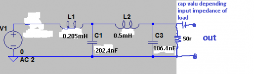
I leave it out of my line amps, but use a 2nd order input filter in my power amps (100k -> 33nF -> 1M -> 22nF -> 510k)
You're right, though. CIn isn't necessary, but also as you know Cin protects the tube from the previous stage if it's output cap is bad or large enough to drive a 1k load, and keeps some LF nasties out.
I leave it out of my line amps, but use a 2nd order input filter in my power amps (100k -> 33nF -> 1M -> 22nF -> 510k)
- Home
- Amplifiers
- Tubes / Valves
- 6V6 line preamp