Scope 1kHz 0dBfs 128DSD file, probe x10, scope set to 10mV/cm & 0.1mS
Attachments
Last edited:
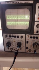
What do you think of these double sinus?Not sure because the frequency readings change as well and that's weird. Oscilloscope will confirm or not. Sinewave peak to peak divided by 2.828 will be RMS.
That delay circuit will do its job but its for driving signal relay regular type as most. I would avoid regular relay on B+. They don't usually have high enough VDC spec, their contacts will be destroyed immediately or soon enough by switching HV. Solid state relays are better in handling such tasks. Maybe too much hassle. Straightforward is the hand switch.
NoDAC looks weaker than 0.56V RMS @ 0dBFs you initially expected. With those DSD test files at least. We don't know enough about it in this thread. Why double sinus etc. Maybe fooling the scope with some noise images it locks on. Further investigate in the NoDAC thread.
NoDAC looks weaker than 0.56V RMS @ 0dBFs you initially expected. With those DSD test files at least. We don't know enough about it in this thread. Why double sinus etc. Maybe fooling the scope with some noise images it locks on. Further investigate in the NoDAC thread.
I use these to switch 300VDC... If you connect the contacts in series, you can switch 600VDC (low current)
https://www.hongfa.com/Product/Item/HF115F-I
Datasheet: https://source.hongfa.com//pdf/web/...duct/PDF/HF115F-I_en.pdf×tamp=1674847695
https://www.hongfa.com/Product/Item/HF115F-I
Datasheet: https://source.hongfa.com//pdf/web/...duct/PDF/HF115F-I_en.pdf×tamp=1674847695
Done, if you want to follow https://www.diyaudio.com/community/threads/simple-dsd-modulator-for-dsc2.370177/page-24That delay circuit will do its job but its for driving signal relay regular type as most. I would avoid regular relay on B+. They don't usually have high enough VDC spec, their contacts will be destroyed immediately or soon enough by switching HV. Solid state relays are better in handling such tasks. Maybe too much hassle. Straightforward is the hand switch.
NoDAC looks weaker than 0.56V RMS @ 0dBFs you initially expected. With those DSD test files at least. We don't know enough about it in this thread. Why double sinus etc. Maybe fooling the scope with some noise images it locks on. Further investigate in the NoDAC thread.
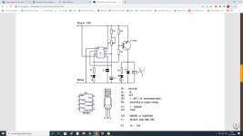
If you insist on using a tube rectifier, there are multiple technologies.
3 of them are:
Direct Heated, 5Y3, 5U4, etc.
Indirect Heated, 5AR4, etc.
Damper Indirect heated 6XXX
They have different warm-up delays
A 5Y3 Rectifier warms up quickly.
But, if you have an extra 6.3VAC winding, then you will get an intrinsic slow warmup delay if you:
Connect 6.3V to a 0.65V series resistor, to the 5Y3 filament, and return the other end of the 5Y3 filament to the other end of the 6.3V.
The hot resistance of a 5Y3 filament is 5V / 2A = 2.5 Ohms
The cold resistance of a 5Y3 filament is a lot less than 1 Ohm.
When 6.3V is first applied, the 6.3V divides between the 0.65 Ohm resistor, and the cold 5Y3 filament.
When the 5Y3 filament warms up, there is 5V across its filament.
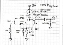
What you can get as max from 0.212V is 1.44V RMS in this circuit if you will disengage the feedback. In other words if you will disconnect Rf and replace/bypass Ri for 1k grid stopper. The 1meg across the input you keep it.
More or less the same gain that I have with the 12B4 x6,5 that I'm just listening now with the bias you adviced B+ 160V 15mA CCS, sounds wonderful.
PCBs came! Man, I wish I had more play money to spring for expedited shipping, that wait was torture!
I was able to strip the old two examples, and populate one each of the new boards, in addition to one of my spiritual companion boards- the noval dual triode boards, in this instance loaded with a couple side-getter clear top RCA 6FQ7.


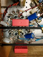
I didn't have more of the huge Wima caps, so the 9AJ board got some old 1.8uf caps from the cookie tin of salvaged parts. Also some random power resistors, so the third board looks a little silly next to the Salas boards.
I really need a solder sucker. Pulling the 7 pin sockets was not fun with just an iron and tapping the old solder away, and then using desoldering braid
Not sure if I'll test and function check them in the next day or so, but I'm already liking the screw terminals for the heater wiring, the three terminals let you run them individually or series depending on how you feed and wire them. It will allow the LM317 CCS, per tube, or using them in series or parallel with a DC or AC voltage supply. I'm assuming a DC supply of some sort is gonna be 90% of the builds but it'll work if desired in AC.
Wile the 6AQ5 has solid centers in the sockets, the devil on my shoulder is trying to convince me to put an LED under the sockets on the 6P43P-E and 6FQ7 boards 😈
For "demonstration purposes" of course 😆
I was able to strip the old two examples, and populate one each of the new boards, in addition to one of my spiritual companion boards- the noval dual triode boards, in this instance loaded with a couple side-getter clear top RCA 6FQ7.
I didn't have more of the huge Wima caps, so the 9AJ board got some old 1.8uf caps from the cookie tin of salvaged parts. Also some random power resistors, so the third board looks a little silly next to the Salas boards.
I really need a solder sucker. Pulling the 7 pin sockets was not fun with just an iron and tapping the old solder away, and then using desoldering braid
Not sure if I'll test and function check them in the next day or so, but I'm already liking the screw terminals for the heater wiring, the three terminals let you run them individually or series depending on how you feed and wire them. It will allow the LM317 CCS, per tube, or using them in series or parallel with a DC or AC voltage supply. I'm assuming a DC supply of some sort is gonna be 90% of the builds but it'll work if desired in AC.
Wile the 6AQ5 has solid centers in the sockets, the devil on my shoulder is trying to convince me to put an LED under the sockets on the 6P43P-E and 6FQ7 boards 😈
For "demonstration purposes" of course 😆

Absolutely love it, thank you so much for doing this! Looking forward for your final thoughts and getting my hands on a pair fo those of course 🙂

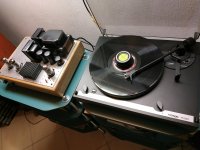
It took me about an hour to convert the 6V6 line preamp to NFB version .I've been listening for a while, I think this version has more details and has better separation and very very silence...On 390Ω resistor i measure 8.10V and 8.30V i use old caps 470uf/100V Philips low esr.and about 317V B+ at the beginning.
Attachments
Last edited:
- Home
- Amplifiers
- Tubes / Valves
- 6V6 line preamp