Fantastic — I am looking to finally build one of these soon. Hoping it might make a good pre for an Accuphase P-300 I’m about to refurb.
I have not forgotten 😉
Too bad I don't know too many locals. Too little time, but it would be nice to pass these around for testing and tryouts. Not enough time in my busy days. I generally only have an hour or two free at a time lately.
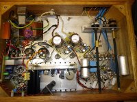
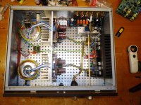
I need to cut out an IEC jack hole next and then mount the transformer I intend to use.
Too bad I don't know too many locals. Too little time, but it would be nice to pass these around for testing and tryouts. Not enough time in my busy days. I generally only have an hour or two free at a time lately.
I need to cut out an IEC jack hole next and then mount the transformer I intend to use.

Looks fantastic! I bet it sounds even better. Hope I will get myself one one day. Planing to wait a little bit longer for those boards as I have sooo many audio stuff to finish 🙂
Nice to hear. I've been putting a lot of CAD design time into a chassis/cabinet for this project, revising, revising, revising! Going for aesthetics since the circuit is so proven already I can just have fun in the shop... Hopefully sometime this summer, here is a preview of the topside so far. The triangular shaped area is going to be machined from 7mm aluminum stock, mirror polished, floating above the walnut top on three posts with bolt heads recessed, toroid, and four potted chokes (LCLCRC followed by an LC for each channel)! those are the rectangles. Handles along the sides of the top. I hate seeing screw heads on chassis tops, so the tube saddle holes will be M3 tapped and screwed up from bottom. The front and rear panels will be inset into the wood, all the wood is walnut, tung oiled. Left and right sides will have two heatsinks imbedded flush with the wood sides in case I decide to use L/R dedicated shunt regulator boards. First cut I will just use LCLCRC with left/right LC, then try regulating later on. Pot will be mounted on back panel with extension shaft to front, (left) is the signals side (right) comes in with the IEC and fuse. Front panel will have power switch and pilot on right, source selector and volume on left. I have a Chinese relay board and rotary switch for source selector. Front panel will have a handy 1/8 inch jack for my portable lossless MP3 player's line out as one of the sources. 5U4G sits in the center of the top, proudly. The two dotted rectangles are interior items, one of them is the DC filament regulator and the other is the 5V flat pack transformer for the 5U4G. etc... I have not done the CAD work for the front/back panels yet, its all so much fun. It is 350mm x 350mm square top. BTW the Antek toroid covers are very nice, it just arrived, the circle is the covered toroid. Its a work in progress screen scrape below...

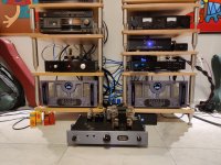
Nick , my friend, I do not change the 6V6 even with the DCG3....hahahaha i have them both .....😊😊Here's a 6V6 diy line pre that I was invited to listen in a friend's system. Trading places with a Manley pre. The 6V6 pre did not shame itself at all.
Attachments
Hi,
Yes, its nice you have them both. To explain...
I have listened to the 6V6 and to a balanced DCG3 with the Manley mono-block amps that day. Their XLR inputs are interfaced with small cylindrical audio transformers inside. There are toggle switches on their slanted backs to select RCA or XLR inputs. When using their balanced inputs about 6dB voltage sensitivity is lost.
The 6V6 pre had more information and a richer cleaner sound than the Manley pre in my humble opinion. The Manley's midrange was kinda reticent with more of a distant U. With the DCG3 balanced XLR build there was blacker background and even more information than from both the tube preamps. The ATC 20 professional monitor speakers sounded even more "studio" style as they should. Deeper and more solid. Mid presence still there without roughness. Less tonal painting vs tubes of course. Both preamps are nice when you got them to can mix them in system variations depending on what aspects are missing more. System gain and type of connection played a significant role here too. Due to the power amps interfacing specifics.
Voltage gain for the inefficient speakers when with weaker than digital sources was better with the tube preamps driving through RCAs. The DCG3 measures better than tube preamps because of its low noise JFET input stage and much NFB, but the 6V6 line pre still had enough S/N to support the Manley monoblocks -80dB 1W unweighted S/N spec.
I also preferred the 250W tetrode amps in half power triode mode. This power was still big enough for the given space and the 20 liters 85dB 5Ω impedance speakers. There was also an active subwoofer augmenting those stand-mount monitors.
I've been throwing around the idea of building this since early in the projects infancy and finally started sourcing some of the parts for the build. I'll be using 7C5 loctals because I have a few dozen sitting around here. Initially, I was planning on building them with everything mounted inside of the chassis, but with my initial design, that would have had the 6V6 mounted horizontally. Do you think that will accentuate microphonic issues? I could probably just increase the depth but I'd rather not. I'd love to hear people's thoughts.
Probably using a landfall systems split chassis with tubes and Heatsink from the sshv2 mounted in an area with perforated material.
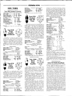
This is from Sylvania News December 1936. Their Introduction of 6V6G. With interesting description. See images. I extracted the text so you can read it better. Member Carter of St Louis sent it to me. Thanks!
Type 6V6G is a beam power amplifier tube
similar in design features to type 6L6G. The
design features which involves the use of directed
electron beams provides for a tube of high
power output, power sensitivity and efficiency
with a low percentage of third and higher order
harmonics.
The second harmonic distortion is somewhat
high in order to reduce the third and higher order
harmonics to a minimum. Elimination of the
second harmonic distortion may be obtained by
using the 6V6G in a push-pull arrangement. If
only one tube is used in a resistance coupled
unit., second harmonic distort ion can be reduced
by generating out -of -phase second harmonics in
preceding audio stages.
Type 6V6G should prove very desirable in
applications where heater and plate current drain
must be maintained at a minimum. In applications where such features are essential, this type
should be more suitable than Type 6L6G
because of the higher heater current and plate
current characteristics of the latter type, with
voltages of the order of 250 volts. Nevertheless,
the type of operation will be very similar since
the tubes involve the same design features.
The heater current rating of 0.45 ampere is
rather low for a power tube having the power
capabilities of Type 6V6G. Two 6V6G's may be
employed in a push-pull arrangement whereby
an output of 13 watts may be obtained when
plate and screen are operated at 300 volts. For
this type of operation the total heater current
for the output tubes would be no greater than
for a single 6L6G. Smaller household receivers
and automobile radios could employ a single
6V6G and provide performance which would be
superior to that obtained from a single output
pentode. The 250 volt rating would be applicable for most automobile receivers.
Attachments


Does that mean 6V6 wired triode also has rather high H2 in its output, but comparatively low H3?
I made a simulation of a pair of 6V6-triodes as an LTP, with a CCS tail. The result is really, really low predicted THD.
Another triode that has high H2 but lower H3 is the 12AT7, correct? At least that's what Eli D wrote about, and it seems plausible.
Are there others like that?
Perhaps if one combines a 12AT7 LTP to drive a push-pull pair of 6V6s the result would be a clean sounding circuit due to the push-pull H2 cancellation being complementary for both those types.
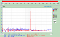
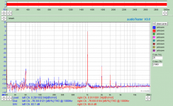
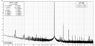
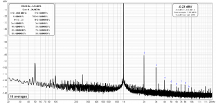
This is how triode wired 6V6s measured in the cathode follower version of this thread's preamp (resistor biased). Definitely 2nd harmonic dominated. Amount of 2nd and hum noise spikes differed between NOS brands. But generally consistent.
Attachments
Salas, your measurements are with the lower voltage and load resistor value, vs the original schematic, correct?
For my CF, I had H2 at -65-70db, and gain version H2 somewhere in the -50's. H3 nonexistent in both cases (-110).
For my CF, I had H2 at -65-70db, and gain version H2 somewhere in the -50's. H3 nonexistent in both cases (-110).
Correct, those charts are from a CF with 330R and 7.7k (33k//10k) at the cathode's divider & 300V B+
Hi. I've skimmed bits of this thread but 15 years and 4000 messages is overwhelming and I can't figure out what the current state of the 6V6 Preamp design is. @Lingwendil has some PCB's but I'm not clear what the status of those are or if they follow the schematic @Salas posted back in 2008 https://www.diyaudio.com/community/threads/6v6-line-preamp.102352/post-1598914? Are there schematics, boards and a parts list for whatever the current state of the design is posted anywhere or commercially available? Thanks.
Check Ling's thread about it. I think he shared a Gerber... AFAIK they are the latest Salas on a board.
Did @Lingwendil start a new thread because I can't seem to find it? Or are you referencing from here on? https://www.diyaudio.com/community/threads/6v6-line-preamp.102352/post-6614282
If he ever shared a Gerber I didn't see it. He seems to have lost some momentum on this project but I'll send him a PM if his work is the latest/most complete version of this project. I guess the couple of posts about completed preamps were made with the test boards he sent out?
If he ever shared a Gerber I didn't see it. He seems to have lost some momentum on this project but I'll send him a PM if his work is the latest/most complete version of this project. I guess the couple of posts about completed preamps were made with the test boards he sent out?
- Home
- Amplifiers
- Tubes / Valves
- 6V6 line preamp