Nice! I´m interested. Thank you very much!Soon 😀
I will do an initial build and test of them, then send a few out to others for testing. We will make any necessary changes to the board, and then do a larger order to sell them to members. Logistics still to be decided there. 😉
Ok, thanks as always. Will investigate.What seems more plausible a scenario is the input circuit needs some kind of investigation about interference since at the pot's max impedance point should be more susceptible.
Or simply compare noise behavior with a smaller value pot.
On the grid leak resistor, what value do you suggest?
It’s only necessary on the gain version, correct?No more than 470K since 6V6 manual says 0.5Meg max for cathode bias circuits
CF already seems always tied to ground via the existing resistor network of 475k right?
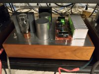
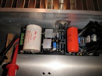
This is my new born 6v6 preamp.
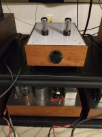
Thanks Salas for the design. It sounds great first start n is burning in at the moment. Sound stage is astonishing good. Sounds very smooth n lush to my surprise.
Thanks Salas for the design. It sounds great first start n is burning in at the moment. Sound stage is astonishing good. Sounds very smooth n lush to my surprise.
Attachments

Salas,
Yes. This is the SSHV 1 that I brought from one member long ago. I'd think the 2 will sound better. I have a tube regulated supply to try on later. Will report the sound difference.
Albert
Yes. This is the SSHV 1 that I brought from one member long ago. I'd think the 2 will sound better. I have a tube regulated supply to try on later. Will report the sound difference.
Albert
Guys, I'm not dead, I swear! Too much going on in life but I am going to try to get back to the PCBs soon. Life has been hectic and I have been unable to focus on many "extracurricular" activities after accepting a new position at work earlier this year.
Need to dig out a transformer for filament supply then I'll try to start laying out a chassis that I can use for initial testing. I have the 6aq5 and 6p43p boards both populated.
Need to dig out a transformer for filament supply then I'll try to start laying out a chassis that I can use for initial testing. I have the 6aq5 and 6p43p boards both populated.
Quick question, (from someone who still has to learn Spice)... I'm building this preamp as the input stage of a fully dual mono headphone amp, dual regulators, dual power supplies, dual everything. I need to know if the HV regulator boards I already have can handle the B+ load plus some... So my question...
How much B+ current does one channel of this project draw from the HT regulator if built exactly to the schematic? Has anyone measured that on a built unit that can help me?
I want to run my tube-hybrid Janus shunt regulator boards on a dummy load overnight to make sure they remain stable for what one channel of this project requires before I proceed. So I need a ma number to start with. Thanks!
I have tried the preamp to work with the tube regulated supply and it sounds with warmer character especially when playing with some sopranos that I like. Sweet
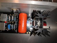
I don't know I brought some sshv2 years ago still sitting in the drawer untouched. I put them up to try but I encountered some sort of problems. I can adjust the current from 10mA to 60mA with no problem. With the 10k dummy load at 20mA, I can't see any voltage at the end. I have the B+ n the sensing joint together, same to ground point n the sensing joint together. Both boards found no voltage at output no matter how I adjusted the 1k. B+390v.
I don't know I brought some sshv2 years ago still sitting in the drawer untouched. I put them up to try but I encountered some sort of problems. I can adjust the current from 10mA to 60mA with no problem. With the 10k dummy load at 20mA, I can't see any voltage at the end. I have the B+ n the sensing joint together, same to ground point n the sensing joint together. Both boards found no voltage at output no matter how I adjusted the 1k. B+390v.
Attachments
In case you energized it before without those connections in place, there could have been a failure. Or the dummy load is too heavy for the output voltage target and drains all of the available programmed current.
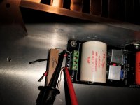
My intention is to put it on my 6v6, but had it tested with lower voltage and current to see if it was working. I can adjust the current but not the voltage. The led didn't come on either. I tested the other one, same result. Where should I start to check first? Only 1.5v at output😊In case you energized it before without those connections in place, there could have been a failure. Or the dummy load is too heavy for the output voltage target and drains all of the available programmed current.
Go to the simplistic MOSFET shunt regs thread. There is a troubleshooting example link in post one.
ThanksGo to the simplistic MOSFET shunt regs thread. There is a troubleshooting example link in post one.
Finally dug out the chassis I was planning to use for my testing and build out of the PCBs. This is eventually going to be a preamp with volume control and 4-way input, 4-way output selection, and a three way crossover. I also gave a few extra jacks for possible expansion. Lots of RCA jacks!
First I drew some layout lines in the vertical and horizontal centers of the top of the chassis with permanent marker. Then I center punched the mounting holes. From there I drilled them out. I gotta say, having the centered hole in the center of the board and sockets made this super easy- definitely doing that on any future board I design.


I didn't make the socket holes all that large as I'm not populating an octal version for myself, I'll be running a seven pin 6AQ5 or noval 6P43P-E. The octal board is dual pattern to also accommodate the 6AQ5.

6AQ5/6V6 combo board with 1/2" standoffs lined up perfectly.


As did the noval board-


Lots of jacks in this thing!

Have to dig up my spare power transformer, and mount one of my populated PSU PCBs in there. Then I can get moving on testing. Both boards fit in just great .

First I drew some layout lines in the vertical and horizontal centers of the top of the chassis with permanent marker. Then I center punched the mounting holes. From there I drilled them out. I gotta say, having the centered hole in the center of the board and sockets made this super easy- definitely doing that on any future board I design.
I didn't make the socket holes all that large as I'm not populating an octal version for myself, I'll be running a seven pin 6AQ5 or noval 6P43P-E. The octal board is dual pattern to also accommodate the 6AQ5.
6AQ5/6V6 combo board with 1/2" standoffs lined up perfectly.
As did the noval board-
Lots of jacks in this thing!
Have to dig up my spare power transformer, and mount one of my populated PSU PCBs in there. Then I can get moving on testing. Both boards fit in just great .
- Home
- Amplifiers
- Tubes / Valves
- 6V6 line preamp