PS: Aren't you all glad that I am re-designing the circuit and asking questions before beginning instead of coming here later for help with an amp that doesn't work! 😀
As I said, this amplifier started out as a learning tool and an experiment where I didn't care too much about the end result. It has served and still is serving its primary purpose as a learning tool. However, as long as I am building it, I might as well make it the best it can be.
Again, I don't mind using two driver tubes if needed instead of one. I also could change to a different driver tube if required, but everything needs to be octal socket not mini. There are five holes on the chassis, and one won't be used because I'm not using the tube rectifier. That's how the choke ended up on the top left. It puts the choke as far away from everything as possible and covers the extra hole. 😀
Last edited:
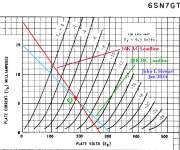
The example of RC coupling using a 6SN7 shows the difference in loadlines of AC vs DC.
People draw loadlines on tubes only to the first step, the DC conditions.
But in reality most tubes in the RC coupled circuit are driving the grid resister of the following tube thru a capacitor.
In this example a 20K plate resister drives a following grid resister of 80K. That all looks like 16K.
The result is the usable voltage swing available on the AC loadline is less than the simple DC loadline would have us believe.
I've picked an extreme case, in the next exciting episode I'll show how to fix that, 👍
Attachments
I'd be building an ultralinear, actually that is what I am planning to build as my first for sale product, a 12AX7-EL34 SE UL unit.Correct. I'd like to try to squeeze as much power out of it as possible. I have no problem with pentode operation or driving the EL34 very hard.
I've picked an extreme case, in the next exciting episode I'll show how to fix that, 👍
Are you advocating for two 6SN7 driver tubes, one driver tube per channel, with the triodes of each tube in parallel? If so, I have a tentative schematic for that but I haven't posted it yet to avoid confusion.
I'd be building an ultralinear
No ultralinear taps on the OPTs that are supposed to come with this kit and untrustworthy specs for the ones that do have UL. That leaves pentode and triode. SEP would be fine with me.
Last edited:
"untrustworthy specs for the ones that do have UL" What transformers are you looking at, as you earlier said you were planning to replace these cheap China ones? There are plenty of great transformers with UL taps.
For the schematic shown on page one the half of the twin triode (6SN7 clone?) is a sufficient driver,
The ratio of EL34 grid resistance to driver plate resistance is low at 2.7. This is a source of even order harmonics.
perhaps the designer had some EL34s that created 2nd harmonic at a similar level. The designer is hoping for cancellation.
Might work at some levels & some tube combinations. But it brings with it higher order harmonics such as the 4th.
All somewhat reduced by the NFB.
I'll use your values on another 6SN7 set of plate curves sometime late Sunday.
More snow to push in the AM here. 👍
What transformers are you looking at, as you earlier said you were planning to replace these cheap China ones? There are plenty of great transformers with UL taps.
More cheap China ones. I'm not spending a lot of money.
The various flavors of these kits come with one of two transformers. One version is rated on AliExpress at 6.5 watts and then there is a slightly more expensive version that has physically larger transformers rated on AliExpress at 10 watts. I assume the smaller ones with no UL tap are intended for triode mode. I'll probably end up getting the larger ones. They aren't very expensive. Even bigger ones are available for a few dollars more. I got the kit version with the smaller transformers by mistake. I checked out with the wrong kit in my cart. My bad. No great loss as they aren't expensive.
I checked again tonight, and the larger OPT version that comes in these kits does have UL taps but no spec for what the UL percentage may be. Here is an interesting rebuild video showing that the ones he got in a pre-built amp were wired backwards from the factory. I didn't even know it was possible for the amp to function that way? His video shows the larger of the two transformers (time stamped), and he is actually using them in UL with a triode switch. -1dB at 8 Hz at 1 watt.
He ended up using three 6SN7 tubes and lots of extra doodads added on. I'd like to avoid that complexity if possible. It's an interesting video series, but I don't want all of the complexity, especially the third driver tube. A link to the "manual" he wrote with his schematics.
https://drive.google.com/file/d/1WpP0oqCUAC_94g3lhbLJvVh8tzgpM_SP/view
I won't be getting his 375VDC. According to PSUdesigner I'll get more like 335. Here is his UL output stage:
Unless UL solves some very real problem in this amplifier like NFB or stability issues, not just "better" specs, why not just use pentode? I have no problem with my little EL84 pentode amplifier. No UL there.
Last edited:
UL does solve problems, it's why people use UL and why they make UL tapped OT vs just wiring everything pentode.
But yeah, if you are buying super low budget stuff from China, who knows what you will actually end up with. Good luck with your project!
But yeah, if you are buying super low budget stuff from China, who knows what you will actually end up with. Good luck with your project!

I agree that Chinese stuff doesn't usually live up to the claims so you have to be prepared to make changes.
But as for Pentode, vs UL, vs triode strapping, just use which you prefer the sound of.
Same applies for feedback or no feedback - everyone has their own preference and opinion.
But as for Pentode, vs UL, vs triode strapping, just use which you prefer the sound of.
Same applies for feedback or no feedback - everyone has their own preference and opinion.
One perspective on your questions is to think about "driving"/"source" impedance and OPT and speaker damping by electrical impedance. IIRC your speakers are DIY fourth order fundamental resonance and were tuned with a valve amplifier as source. We apes are very sensitive to changes in frequency response over critical ranges, and even geezers like me can still hear a small dB change if there's a resonance involved. It's possible, maybe even probable, that the thing you like about those little pentode amps is that they have the correct source impedance for your speakers, and so the correct frequency response and damping. Note that source impedance to the speakers can always be increased with a small resistor; even adjustable.
Source impedance to the OPT is slightly different (it sees a parallel combination of the output valve(s) output resistance and reflected load impedance) than the speaker's source (the secondary of the OPT is changed from that primary parallel impedance by the residual imperfections of the OPT). Negative feedback from the OPT primary is championed by modern builders like stephe because it relaxes some demands on the OPT itself, at the cost of not correcting residual errors of the OPT, as would happen if feedback is taken from the secondary. Modern thought and better modern OPTs make this look better all the time.
The term "UltraLinear" is a branding move from the late 1950s; there's no secret sauce in 43% tap by turns. It works pretty good for Golden Age amplifiers with triode mu of 8 output valves like the contemporary faves in the 6L6-KT88 class, but it's not inscribed on a tablet found in Hawthorne, California. Any G2 ("UL") feedback does slightly reduce source resistance to the OPT (very roughly, half), so is worthwhile that way. If this reduction in source impedance to the speaker is undesirable, that can be easily adjusted with a small resistance pot in the speaker line, maybe 0-2 Ohms, and still maintain the advantages to the OPT.
All good fortune,
Chris
Last edited:
I agree that Chinese stuff doesn't usually live up to the claims so you have to be prepared to make changes.
But as for Pentode, vs UL, vs triode strapping, just use which you prefer the sound of.
Same applies for feedback or no feedback - everyone has their own preference and opinion.
Thank you! 👍
The term "UltraLinear" is a branding move from the late 1950s
It was marketing primarily IMHO. Looks good on paper/scope = money. Not necessarily sound. I will say that I have two amps using UL.
What I have is a set of specifications, that many may disagree with, that I would like to achieve for an as-yet unbuilt amp, regardless of all of the other arguments. Here is what we have:
- I need a SE EL34 circuit design that works well, with a minimum chance of instability, preferably with the 6SN7 driver tube(s) and with the circumstances below
- A circuit design that will provide adequate gain
- GNFB is fine to the extent needed to achieve other design goals including power and stability
- I have a power supply that should yield around 335 volts
- Iron that is known to work just fine for many thousands of people when built correctly
- Frequency and power response that is clean down to at least 25 Hz
- As many watts as possible, right down to the last possible watt at 25 Hz
- A damping factor that is minimally acceptable because my speakers just don't care - they are not designed that way and deliberately were not
So please, let's try to focus on the bullet point specifications above, and whether or not it is possible to achieve them, and if so what the tradeoffs are to get one spec versus the other.
Last edited:
You haven't said what the maximum distortion % is acceptable and over what frequency range.
If you want more power, then consider parallel EL34s (with half the OPT resistance)
I highly recommend Glassware Audio's SE AMP CAD program. You can have hours of fun trying different permutations of tube, designs and OTPs.
(You will have to run it in XP compatibility mode in Win 10 or 11.)
https://glass-ware.stores.turbify.net/seampcad1.html
You haven't said what the maximum distortion % is acceptable and over what frequency range.
I don't have a distortion spec, and it varies wildly depending on who you ask. Some say 5% and some say 1%. Frequency range? Yes, we need to hit 25Hz as cleanly as we possibly can and with every possible watt or fraction thereof. As far as top end, I used to be able to hear 22kHz. I still can hear 18kHz, and let me tell you, a tone that high is about as annoying a screech as can be imagined. I'd say that -1dB at 18kHz would be just fine. I have no desire at all to go above that, unless required to get stability. As far as audibility, no.
If you want more power, then consider parallel EL34s (with half the OPT resistance)
Given that the chassis only has five holes in it, and iron that is rated for 10-13 "Chinese" watts, parallel EL34 doesn't seem possible in this case. If I build an amp from scratch, maybe, but that puts me right back to the heat thrown off by the wanna-be fireplace known as my Dynaco ST-35 series ii with its four EL34 output tubes roasting everything around it. I forgot to mention that it's why I don't keep using it. My Dynaco ST-35 also is a little fireplace, but it's a smaller fireplace than the ST-70 ii.
Last edited:
No need to bristle; I'm only trying to help build a foundation from basic principles up. Frequency response and damping are fundamental to making amplifiers, not ephemera. What you're working to learn is a multi-faceted subject, and one where some fundamentals are too often glossed over, then often misunderstood, then often replaced with Lore, a poor substitute. All speakers, especially multi-driver with internal crossovers and fourth order HP boxes, are strongly influenced by source impedance. It's not a sin; it's just part of engineering.There is no "preference" for one damping factor or one amplifier design or the other.
So please, let's try to focus on the bullet point specifications above, and whether or not it is possible to achieve them, and if so what the tradeoffs are to get one spec versus the other.
The impedance at the interface between amplifier and speaker is a large part of the tradeoffs in amplifier design, and the impedance between output valve(s) and OPT is almost as important, at frequency extremes.
All good fortune,
Chris
My Chinese Se amp in the link posted earlier is good for about 10watts but I only wanted it to drive the Scanspeak tweers in my Naim SBL speakers so LF response wasn't important.I don't have a distortion spec, and it varies wildly depending on who you ask. Some say 5% and some say 1%. Frequency range? Yes, we need to hit 25Hz as cleanly as we possibly can and with every possible watt or fraction thereof. As far as top end, I used to be able to hear 22kHz. I still can hear 18kHz, and let me tell you, a tone that high is about as annoying a screech as can be imagined. I'd say that -1dB at 18kHz would be just fine. I have no desire at all to go above that, unless required to get stability. As far as audibility, no.
Given that the chassis only has five holes in it, and iron that is rated for 10-13 "Chinese" watts, parallel EL34 doesn't seem possible in this case. If I build an amp from scratch, maybe, but that puts me right back to the heat thrown off by the wanna-be fireplace known as my Dynaco ST-35 series ii with its four EL34 output tubes roasting everything around it. I forgot to mention that it's why I don't keep using it. My Dynaco ST-35 also is a little fireplace, but it's a smaller fireplace than the ST-70 ii.
Not sure what power out you'll have at 25Hz using the smaall Chinese iron - you'll have to download the free REW software and do some measurements.
https://www.roomeqwizard.com/
It's a lot more than for room equalisation: includes a scope, sig gen, RTA, Level meters etc. It's a must for any audio diyer in my opinion and the Behinger UCA222 interface is under £25 (on offer at £20 from Amazon)
Of course you can spend you life experimenting with circuit designs and component values but at least a kit is a starting point.
No one has suggested using a constant current anode load as I do using an Ixsys10M45. A preset can make the current adjustable.
https://uk.farnell.com/ixys-semiconductor/ixcp10m45s/current-regulator-450v-0-01a-to/dp/3438365
Inevitably, you'll have to distill the suggestions or your brain will explode, as mine has done several times....
If you want something proven, have a look at Tubelab SSE. Very well documented and supported.
http://tubelab.com/designs/tubelab-sse/
http://tubelab.com/designs/tubelab-sse/
@Never Get Old :
I don't know if it has been mentioned already, but if it was me, I would promptly shift the power transformer and the left output transformer's positions, according to the green arrows below :

So you would have really ALL the supply at the left...
But it's me, OK ? 😉
Aw ! Sorry : the chassis is probably already punched and drilled... Too bad ! 😕
T
I don't know if it has been mentioned already, but if it was me, I would promptly shift the power transformer and the left output transformer's positions, according to the green arrows below :
So you would have really ALL the supply at the left...
But it's me, OK ? 😉
Aw ! Sorry : the chassis is probably already punched and drilled... Too bad ! 😕
T
Last edited:
Discussions where folk are typing at each other is immediate, and very often enough, but has its limitations for technical subjects. An important variable for technical subjects, yet difficult to express, is relative importance, the weighting or significance of the very many contributors to performance.
An example from OPTs: all practical OPTs are close enough to perfect over a wide middle range of signal level and frequency. But at extreme ends of the design range of both level and frequency, practical OPTs approach their limitations of perfection, and nudge us for attention. There is no such critter as an IEC weighting curve for OPT performance, no standard reduction of a curve into a single number, either for LF or HF limitations or signal level limitations. I would never minimize "rules of thumb" on this account - approximations are no sin. But, Lore is a step away, and can be very, very unreliable. As much as possible, we're better off with, but only if actual/well described/verifiable/applicable, numbers. Numbers plural, because anything really important is not linear with signal level or frequency. My take-away is that anything pretending to be a Figure of Merit is inherently flawed. Just look at modern American politics for an evolved worst case example. Arf.
For OPTs, at LF the important numbers are primary (magnetizing) inductance at various levels at low audio frequencies (and, for push-pull, at various DC imbalances), and at HF can practically be reduced to leakage inductance (as measured at some representative "high" frequency) and lumped-sum capacitances measured at external terminals (not really really real, but seems to be, so ). A reasonable model at HF is the simple lumped-sum model, and at LF some worst case can be taken for stability judgements, noting that large signal is often worst case.
All good fortune,
Chris
ps: Heard on the radio about a couple who discussed mutual topics on a 1 thru 10 scale. "I'm about a 7 on that." "I'm a 3". "Well, maybe let's not go." Weighting with attempted dis-ambiguity.
and uhhh....I don't think you can get 25Hz on a shoestring budget. Bass needs a big iron core and them Sheetz ain't cheap.
I rechecked my Oriental SE amp. (1, 6SN7GT per channel in cascode configuration, 1, El34/KT77 output, 8r resistive load)
You can see how the low frequency phase and distortion results are not brilliant below about 40Hz.
My OTPs look about the size of the OP's.


You can see how the low frequency phase and distortion results are not brilliant below about 40Hz.
My OTPs look about the size of the OP's.
- Home
- Amplifiers
- Tubes / Valves
- 6SN7 + EL34 SE stereo amplifier build - questions