Hey-- quick question for the team:
I'm a little concerned about the overall input sensitivity for the amplifier given that it was my intent to have it driven directly from a phono preamp. It looks like I'll need about 2.2V to drive it to clipping, but even if I squeeze 48dB out of the phono stage, I'll still only get about 1.3V of input voltage, with a 40dB gain providing only a .5V input.
Should I be overly concerned about this? I suppose I could bypass the cathode of the input 12AX7 to increase gain, but that would just be a bandaid for the larger issue of needed voltage I can't provide from a phono stage.
Any thoughts or ideas would be appreciated. Construction update to follow shortly.
Kofi
When you say "2.2V to drive it to clipping," is that RMS or peak signal voltage?
What input signal voltage to the RIAA preamp are you using to figure its output signal voltage?
I usually use 5mV RMS (7.07mV peak) for the nominal input signal voltage at 1kHz from a 'typical' MM cartridge.
40dB of gain = 100x gain, so 5mV * 100 = 0,5V (500mV) RMS. That's 0.707V peak for the nominal level.
Peaks can be +15dB or more than that (like record pops and clicks). 6x gain = 15.6dB gain.
0.707V peak * 6 = 4.24V peak maximum output from the phono stage (3V RMS).
You should be able to clip the amp with any pop or click on the record with the volume control all the way up.
I think...
I could be wrong, though.
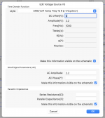
Hmmm...
Thought that LTSpice would have been calculating using RMS for the AC amplitude, but maybe not. I'm using 5mV input as well. Just got worried that I would not be able to push the amp with such a low voltage given the current gain, but maybe I'm being paranoid...
Kofi
Thought that LTSpice would have been calculating using RMS for the AC amplitude, but maybe not. I'm using 5mV input as well. Just got worried that I would not be able to push the amp with such a low voltage given the current gain, but maybe I'm being paranoid...
Kofi
Attachments
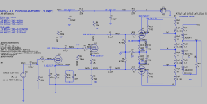
You could split R13 into two 1k resistors, with the bottom 1k left unbypassed, the top 1k bypassed with 220uF, and the feedback connected to the top of the bottom resistor ( = the bottom of the top resistor).
You'd have to recalculate the values or R14 and C8 to get that 6.5dB of NFB.
You'd have to recalculate the values or R14 and C8 to get that 6.5dB of NFB.
That's an interesting move. I was actually thinking about a way to eliminate only some of the degenerative feedback and what you described would do the trick. I'll see how it goes as is since I'm nearly done and I'll cook up a variation in LTSpice and see where that gets me in case I wind up needing it.
Thanks as always for the reply. Really appreciate it.
Kofi
Thanks as always for the reply. Really appreciate it.
Kofi
Not all waves are sine; in LTSPICE's world, most are not. Spices usually work on Peak.Thought that LTSpice would have been calculating using RMS
Would that be a total disaster?got worried that I would not be able to push the amp
Gain adjustment and control is a key skill of the audio worker. I would normally bring up a new system 30dB below clipping first-trial, and slowly push up to clipping. Yes, ultimately I want every Watt I paid for! But adding a 10dB-20dB line stage is a VERY old technique (over a century).
Ok, gang. Finished up the wiring tonight. Had to add some wirewounds heat-sinked to the chassis on the secondary of the transformer to drop some voltage (OK-- initially, I accidentally added them to the primary side, then rewired to fix it).
Voltage was still too high, but I dialed it back with a variac and got the B+ around 400VDC for some testing. IIRC, these Antek toroids have a tendency toward over-voltage, so I may need to drop a little more...
Anyway, it looked to me like there was an issue with the heater on the 12AX7 (6L6GCs and 12AU7 have the glow), but before I could start testing the B+ dropped to 14V. Fuse still seems to be intact, but I'm too tired to do more tonight.
I'll report back once I have more data.
Kofi
Re-check your work. ECC83 heaters are hard to see,they're only diddy things. On all the amps I've built I've done several daft things or forgotten to wire something up. It's a good idea on first power up to crank the mains up to about half so that heaters are doing some heating and the circuit starts to pop into life. At this point I usually get the odd smoking resistor or nothing happens. Several face palm's later things start to work, then check DC conditions.Anyway, it looked to me like there was an issue with the heater on the 12AX7 (6L6GCs and 12AU7 have the glow), but before I could start testing the B+ dropped to 14V. Fuse still seems to be intact, but I'm too tired to do more tonight.
Last edited:
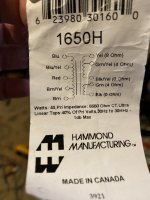
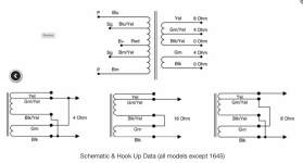
Yep. Did just that. So, the heaters are fine but I connected the transformer wrong initially. I used the stupid sticker that came with the transformer and didn't look closely enough at the windings. Note the difference between the sticker and the wiring diagram on Hammond's site.Re-check your work. ECC83 heaters are hard to see,they're only diddy things. On all the amps I've built I've done several daft things or forgotten to wire something up. It's a good idea on first power up to crank the mains up to about half so that heaters are doing some heating and the circuit starts to pop into life. At this point I usually get the odd smoking resistor or nothing happens. Several face palm's later things start to work, then check DC conditions.
So, now I am getting an UNGODLY HUM when I hook up speakers. It is INSANELY loud and does not change when moving the volume pots around. Both channels. Really bad.
I'm gonna go poking around with a scope but any ideas would be appreciated. Ya know. If ya got 'em.
Kofi
Attachments
I'm thinking the likely culprit is a ground loop caused by yours truly. I was really worried about safety grounding and this is my first amplifier with three separate panels (front, back, top) inside a wood chassis. I connected each panel electrically with what I thought was a safety ground, but it's possible that I'm injecting PSU currents into the negative speaker terminal instead.
Thoughts? If so, how SHOULD I safety ground the amplifier given that there are separate panels?
Kofi
Thoughts? If so, how SHOULD I safety ground the amplifier given that there are separate panels?
Kofi
Is it bolted together? The bolts/screws connect the metal panels electrically, so no grounding wires needed. Remove the grounding wires and check continuity. The ground bus should be attached to the chassis either at the RCA IP or at the first voltage amplification stage.how SHOULD I safety ground the amplifier given that there are separate panels
To suss out the hum first check what flavour it is; is it 50hz or 100hz, that will narrow things down. Is the hum on both channels (that's if it's a stereo amp)? If so that points to a power supply issue, check your ripple voltage on your HT/B+, just flick your meter onto AC volts. Another wrinkle is to pull the voltage amplification valve, it won't effect HT much,does hum go away?
Andy.
Last edited:
Thanks, Andy.
I've got something loose somewhere for sure since it only seems to power up when it's upside down. I'd love to qualify that as a feature, but I can't see how right now.
The voltage and current measurements are essentially perfect, so it's got to be a either a ground loop, some (additional) miswiring of the OPTs or maybe the feedback loop. I'll put it on a scope this weekend and try to suss it out.
Stay tuned.
Kofi
Ahhh, an Australian amp : ) Try going over the whole amp, all the solder connections with a magnifying glass. Another essential fault finding tool is a stick, a non conductive one, give likely connections a prod. A gentle thump here and there might be instructive whilst intently looking at areas like power supply. You could try pulling ground connections and moving them with a jumper lead to remove any ground loops.I've got something loose somewhere for sure since it only seems to power up when it's upside down
Lastly another thing to check is transformer alignment, are your OPT's 90 degrees in relation to your mains tfmr? Is the mains tfmr too near your input/voltage amplification stage? Finding out whether hum is 60/120hz with give you a clue. Post some good pictures here,we might spot something you've missed.
Andy.
Last edited:
So! Let's talk about all the things Kofi found!
Crazy-Goofy Amplifier
By Kofi Annan
AC neutral's broken wire
(Fixed when B+ went haywire)
Smoked resistor for the screen grid
(Grounded, mister. Threw a mean fit)
Power! O no! Just a trickle?!?
(Loose connection, gave a wiggle)
Thump, thump, thump on output, see?
(Pulled the global NFB)
Now it plays a mighty tune
Needs to get some feedback soon
Much distortion? Yes, a little.
With feedback I now must fiddle
Anyhoo, it was the NFB causing the insane hum. I'm running it open loop now, but will need to add some feedback to get things into place. I mean, it really sounds great right now, but it's really wild. I wonder if the transformer was grousing about the NFB since I was sourcing it from the same 8-ohm tap for the speakers?
Also wondering if I need to take into account the fact that the 1650H Hammond OPT has a bit of a funky output configuration? I've attached a scope pic of the impact the NFB had on the output for reference.
Any advice on NFB for this guy?
Kofi
Attachments

Things to check, I half wondered if you were applying positive FB but that will increase THD not necessarily hum,that waveform is horrible though,what's it like at 1khz & 10khz, the same? Looked at the 1650H sec winding,have you got it wired right? Someone on another thread were saying their Hammond OPT had an incorrect colour ID/code, worth checking with a meter and or sig gen. Is the 0v tap connected to ground?Anyhoo, it was the NFB causing the insane hum
After your sure it's wired correctly get a 20k or whatever 10 turn pot if you have one and wire in place of the NFB resistor, set to max R then reduce monitoring OP and THD, if both go up, something's wrong. Lastly if it were mine I'd do repeated frequency sweeps checking each stage, remember to use a x10 probe though.
Anyroad, it sounds like your slowly getting there, it's a pain in the **** but a good learning experience, just keep swimming as the little fish said, Andy.
Last edited:
Thanks, Andy. I'm going to open it back up this afternoon and I'll report back. It really is some very nasty feedback. I also thought it had to be positive feedback as well, but I'm pretty sure I wired the transformer properly (at least according to the diagram): green-yellow attached to green, black-yellow attached to black and speaker - /0V / ground, yellow attached to speaker +.
I think I have a variable air capacitor that I ripped out of an old tuner somewhere. I remember using it to tune the feedback on my Bevois Valley amplifier (Morgan Jones, Valve Amplifiers), so I should be able to use that and a trimpot to try to dial in something that doesn't puke into the voltage amp. Failing that, I'll have to desolder the secondaries and run some resistance and continuity measurements.
More to come soon. Really appreciate all your help and encouragement.
Kofi
LT Spice has enamored many here on DIY in the last while. Looks to me that has resulted in much wheel spinning.
And crazy expectations & results.
Whatever happened to carefully studying schematics & using 4-function calculators to check
if resulting currents & voltages are where they should be?
In the dark ages all was done with pencil & paper. And a slide rule.
In most cases the amps built ran first time right out of the gate.
Unless a bad solder joint!
Attachments
OK, so it looks to me like I'm shooting positive feedback into the input tube cathode from the transformer secondary. Just ran a square wave test of the amp and with 'negative' feedback the waveform grows in amplitude. When I remove feedback, the square wave decreases in amplitude. I feel like I have it wired correctly for an 8-ohm tap according to the diagram provided by Hammond, so I'm guessing this means that either the wire coloring for the secondary may be off or I have somehow reversed the primary leads.
Think this is what you suspected earlier, Andy, so sounds like you might have won a prize here. I presume there's a simple way to test the leads, but I'm guessing I'll have to disconnect them from the amp first?
Kofi
Think this is what you suspected earlier, Andy, so sounds like you might have won a prize here. I presume there's a simple way to test the leads, but I'm guessing I'll have to disconnect them from the amp first?
Kofi
- Home
- Amplifiers
- Tubes / Valves
- 6L6GC UL PP Fun Time!