I can certainly see what you mean here. I could definitely have used a more capable driver. I'm assuming something in the *SN7 family may be better.
Not sure if its worth the re-work necessarily but something for me to chew on for sure.
Kofi
Before you look at any changes, I may not have as good understanding of how the Cathodyne handles signal in/out with respect to what we normally see in a VA or output stage when it comes to G/K voltage realtionship. If the normal difference where the grid is (-V) to the K applies, then that difference needs to be as high as the output signal you want to send to the finals. But if the PI can still pass whtever you put on its grid...( the output of your VA) then ..keep on keepin' on. That would be the case if the K voltage falls and rises as fast as the grid. The normal relationship would hold. This may be a ..Duh, moment.
Last edited:
Hey hey!!
Finishing up the parts list for this and I'm wondering if I'm going to be able to find a suitable first capacitor. The ripple current is a lot higher than I'm used to (given the increase in current required by the supply) and PSUD is measuring about 1.5A of steady state ripple on the 12uF.
Any thoughts on this?
Kofi
That simulation is invalid. There is no allowance for the primary & secondary PT resistances.😱
Well, it's close to the secondary DCR alone. Multiply primary DCR by turns ratio squared and add that, or have PSUD do it for you...
PS Calc Rule of Thumb
From Post #18 it appears the PS for the PP UL 6L6GC amplifier pair is 290 ma at 480V, 1655R.
A good target for the size of the first cap in a cap input filter is to calc for the condition that
20 = 2*PI*f*Rl...............for a 60 Hz supply 2*PI*f is ~377
So with nothing more than a four function calculator the cap is found to be 32 microF. This results in a reasonable ripple component in the DC & rms current in the PT that avoids excess heating.🙂
The following LC filter will do the rest.
@Kofi - I'm sure you could rejigger the design from 12AT7 to 12AU7 with little effort.
Thanks. Sorry again for the delayed response. Wound up on a bunch of interviews and will be changing jobs for the better. Good news is I will have about a month off between jobs, so plenty of tinkering time!
I did indeed swap the 12AT7 for a 12AU7A. I had to fiddle a bit, but I believe the attached schematic should work. Power is increased to about 29 watts with a 2.5V signal input with .73% THD. Not bad.
Looks like the 12AU7A will tolerate a 100V difference between heater and cathode, so I believe I'm OK to raise the cathode voltage a bit.
I'll review the PSU stuff later tonight, but thoughts on my changes would be appreciated.
As always, thanks for everything.
Kofi
Attachments
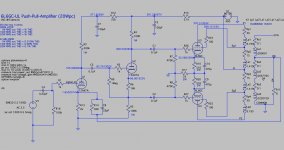
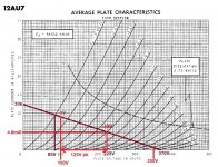
You have the 12AU7 biased very cool, with something like -13V grid bias. I really don't think that's necessary.
Using 100k plate and cathode load resistors on the 12AU7 cathodyne is equivalent to using a 200k plate load resistor on it as a common cathode stage. You have the 12AU7 operating with Vp = 200V and Ip = 0.92mA. I think you want more current drawn through the 12AU7 so it can more effectively drive the 6L6 grids (especially important at levels where the 6L6s will go into AB1 operation).
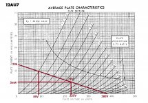
Looking at the ever-lovin' loadlines for 12AU7, I think it might be worth trying the following:
R4, R5 = 15k ohms 2W
R6 = 2k ohms 0.5W
Vp-k = 225V
Vg = -10V
Ip = 5mA
Each triode of the 12AU7 will be dissipating 1.15W, which is well within its safe operating range (2.75W max).
A 15k ohm resistor with 5mA through it will drop 75V, so the 12AU7 cathode will be at +85V or close to it. That's fine for the cathode-heater voltage.
Give the above a try in LTspice, see what it says.
Oh, and by the way,
You have plenty of B+ available for using a 12AT7 as the cathodyne, which could work very well there...
--
Using 100k plate and cathode load resistors on the 12AU7 cathodyne is equivalent to using a 200k plate load resistor on it as a common cathode stage. You have the 12AU7 operating with Vp = 200V and Ip = 0.92mA. I think you want more current drawn through the 12AU7 so it can more effectively drive the 6L6 grids (especially important at levels where the 6L6s will go into AB1 operation).
Looking at the ever-lovin' loadlines for 12AU7, I think it might be worth trying the following:
R4, R5 = 15k ohms 2W
R6 = 2k ohms 0.5W
Vp-k = 225V
Vg = -10V
Ip = 5mA
Each triode of the 12AU7 will be dissipating 1.15W, which is well within its safe operating range (2.75W max).
A 15k ohm resistor with 5mA through it will drop 75V, so the 12AU7 cathode will be at +85V or close to it. That's fine for the cathode-heater voltage.
Give the above a try in LTspice, see what it says.
Oh, and by the way,
You have plenty of B+ available for using a 12AT7 as the cathodyne, which could work very well there...
--
Attachments
Last edited:
Thanks, Rongon.
Sorry to be such a trainwreck here, but I was under the impression that I needed to run it at a lower current for the PI.
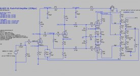
Here's the new version, entirely based on your recommendations.
Also, I originally had the PI as a 12AT7, but understood from this thread that the AU7 would provide greater drive for the 6L6GCs. It would be on brand for me to have misunderstood that, of course.
Kofi
Sorry to be such a trainwreck here, but I was under the impression that I needed to run it at a lower current for the PI.
Here's the new version, entirely based on your recommendations.
Also, I originally had the PI as a 12AT7, but understood from this thread that the AU7 would provide greater drive for the 6L6GCs. It would be on brand for me to have misunderstood that, of course.
Kofi
Attachments
I think the question of 12AU7 vs. 12AT7 depends on what you mean by "drive".
I think of drive from a phase splitter as being composed of two things:
1) Current to charge input capacitance of the output stage, and
2) Voltage swing to swing the grids of the output stage *plus* whatever extra voltage gain is required to overcome the loss of sensitivity brought about by applying negative feedback.
Because the 12AU7 has relatively low mu (about 20), the phase splitter will have a bit more insertion loss if made from a 12AU7. Figure gain of the phase splitter will be about 0.92x.
Because 12AT7 has high mu (about 55), a 12AT7 phase splitter will have less insertion loss (and lower THD). Figure the gain will be up around 0.96x or so.
For sinking current into the 6L6 grids, since 12AU7 has a larger grid base it will bias up with a larger negative grid bias than 12AT7, so it can be run with higher plate current than possible with a 12AT7. But of course, if you bias the 12AU7 at only 1mA plate current you've just discarded that advantage.
The 12AT7 can be run well with plate-cathode voltage of 200V and plate current of 3mA. That should still be enough current from the cathodyne to keep the output stage from slew limiting.
Remember that the cathodyne phase splitter is a 'follower' -- its grid goes up and down with the incoming signal as long as there's enough B+ to keep the cathodyne from running into cutoff.
It's all a bunch of compromises, in every direction. The trick is to come up with the very best set of compromises that give up the least to get the best possible performance. For every change you make, you have to compensate with changes elsewhere. Like for instance...
With the 12AU7 using 15k plate and cathode load resistors, try reducing the value of R15 to 2.7k (leave C3 at 100uF). That will bring the B+ up. allowing just a bit more voltage headroom from the driver stages.
I think the question of 12AU7 vs. 12AT7 depends on what you mean by "drive".
I think of drive from a phase splitter as being composed of two things:
1) Current to charge input capacitance of the output stage, and
2) Voltage swing to swing the grids of the output stage *plus* whatever extra voltage gain is required to overcome the loss of sensitivity brought about by applying negative feedback.
I was certainly not taking into account the current drive requirements here. So, I did some googling and a little math on this (from an old SY post) and I believe I understand this better.
With an f3 of 20kHz, and assuming a full-power swing to the 6L6GCs of 32.5V (6L6 bias point) and a 12.5pF grid input capacitance, I believe the calculation would be (again, cribbing from SY):
I = 2*PI*V*C(input)*f3 = 2*3.14*32.5*1.25e-11*20000 = .5mA
I am assuming I would need to double the current requirement for a push-pull stage to get to a total current charge requirement of 1mA. This would mean my earlier fubar on the idle current of the 12AU7 PI would have been a real problem.
I believe this simple formula is not taking into account the impacts of slew rate (or assumes there is none), which would cause additional issues with a 1mA current supply.
Looks like the bias point you recommended for the 12AU7A would supply a little over 5mA in current with am 84V peak-to-peak swing. The 12AT7 in the prior iteration is currently set to supply 3.2mA with a 40V peak-to-peak swing. So far, it seems that the 12AU7A would be the pick.
Because the 12AU7 has relatively low mu (about 20), the phase splitter will have a bit more insertion loss if made from a 12AU7. Figure gain of the phase splitter will be about 0.92x.
Because 12AT7 has high mu (about 55), a 12AT7 phase splitter will have less insertion loss (and lower THD). Figure the gain will be up around 0.96x or so.
Is the insertion loss a function of the gain here? Seems like it, but wanted to confirm.
For sinking current into the 6L6 grids, since 12AU7 has a larger grid base it will bias up with a larger negative grid bias than 12AT7, so it can be run with higher plate current than possible with a 12AT7. But of course, if you bias the 12AU7 at only 1mA plate current you've just discarded that advantage.
"Discarding the Advantage" is pretty on-brand for old Kofi here.
The 12AT7 can be run well with plate-cathode voltage of 200V and plate current of 3mA. That should still be enough current from the cathodyne to keep the output stage from slew limiting.
Remember that the cathodyne phase splitter is a 'follower' -- its grid goes up and down with the incoming signal as long as there's enough B+ to keep the cathodyne from running into cutoff.
It's all a bunch of compromises, in every direction. The trick is to come up with the very best set of compromises that give up the least to get the best possible performance. For every change you make, you have to compensate with changes elsewhere. Like for instance...
With the 12AU7 using 15k plate and cathode load resistors, try reducing the value of R15 to 2.7k (leave C3 at 100uF). That will bring the B+ up. allowing just a bit more voltage headroom from the driver stages.
Yep. And that gives us the ~5ma+ of drive current and 84V peak-to-peak for the PI using the 12AU7A. Sounds like a winner to me.
Rongon-- thanks so much for explaining this so clearly. I hope I digested what you said correctly, but please let me know if I'm off base.
New schematic image attached.
Kofi
Attachments

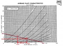
It looks to me like both 12AT7 *and* 12AU7 are up to the task.
- 12AT7 has higher mu, so less insertion loss, slightly less gain required from the 12AX7 so slightly lower THD in the amp output. However, grid current limitations mean slightly less voltage swing available from the 12AT7, but still looks like enough with a little left over.
- 12AU7 has lower mu, so more insertion loss, requiring slightly more gain from the 12AX7 so slightly higher THD in the amp output. More voltage swing is available from the 12AU7, and its output impedance is going to be a little bit lower, so performance of the amp at highest output levels should be slightly better than if using 12AT7.
I've included loadlines for both to show what I'm thinking here.
I don't know which is 'better'. They both look pretty good.
Perhaps someone more knowledgeable than I can point out a good reason to pick one over the other.
__________________________
EDIT TO ADD:
As far as plate current in the driver stage is concerned, you want enough for the driver stage to be able to sink that current into the input capacitance and resistance (in other words, the impedance) of the output tubes' grids. I figure the input capacitance of an ultralinear-loaded 6L6GC must be about 20pF to 30pF, so we do need a bit of current to charge that capacitance at higher than audio frequencies.
Remember that you've added negative feedback which will try to compensate for the falling frequency response of the output transformer by boosting treble frequencies coming from the voltage amp and cathodyne stages. Signal levels at very high frequencies will be a little bit higher than anticipated, so the driver will need to swing more volts to achieve flat response at the output.
The formula for calculating the required current to sink into a capacitative load, avoiding slew limiting at a given frequency is:
I = C * 2 * pi * F * Vpeak
I would design for no slew limiting with up to 35V peak (70V peak-peak) at 50kHz, minimum. Let's make that 100kHz, just to be super-safe. (That's my opinion on this, others may disagree.)
Cload = 30pF
Vpk = 35V
F = 100kHz
Ip required from driver = 0.57mA
Yup, that's all! Either the 12AT7 at Ip = 3mA or the 12AU7 at Ip = 4.8mA will provide massive overkill, good for AB1 operation, but...
A 12AU7 with Ip of only 0.9mA might be cutting it too close.
Attachments
Last edited:
Hey!
Sorry about the blackout. Started a new job and still adjusting...
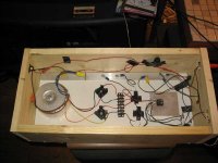
So, I went ahead and got the project started. Wanted to share some of my efforts.
First, I attached the BOM (.zip Excel file) in case anyone wants to review. Mostly orders from Mouser wherever possible, but some from other sources as needed.
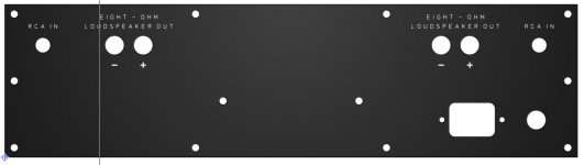
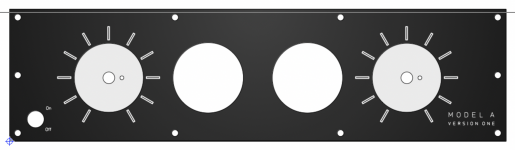
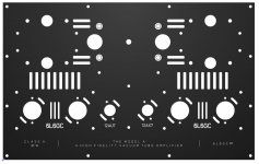
Second, I designed the front, back and top plates in Front Panel Designer. Total for them to fabricate was about $400 shipped, but this is for a rich client (my father) and he ain't care about no budget.
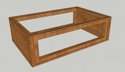
Third, I designed the wood chassis in SketchUp and exported to a .dwg for a local CNC shop to fabricate (still waiting on cost estimates from them). Chassis will be Padauk hardwood (fairly inexpensive and locally available).
I have attached images and files in case anyone wants to see. Build will start next week and I will update as I go.
Thanks a million to the community, especially rongon for managing my amateurish approach and for all his design work. You are the best.
Kofi
Sorry about the blackout. Started a new job and still adjusting...
So, I went ahead and got the project started. Wanted to share some of my efforts.
First, I attached the BOM (.zip Excel file) in case anyone wants to review. Mostly orders from Mouser wherever possible, but some from other sources as needed.
Second, I designed the front, back and top plates in Front Panel Designer. Total for them to fabricate was about $400 shipped, but this is for a rich client (my father) and he ain't care about no budget.
Third, I designed the wood chassis in SketchUp and exported to a .dwg for a local CNC shop to fabricate (still waiting on cost estimates from them). Chassis will be Padauk hardwood (fairly inexpensive and locally available).
I have attached images and files in case anyone wants to see. Build will start next week and I will update as I go.
Thanks a million to the community, especially rongon for managing my amateurish approach and for all his design work. You are the best.
Kofi
Attachments
-
 Screen Shot 2021-12-03 at 10.37.39 AM.jpg70.5 KB · Views: 112
 -
 Screen Shot 2021-12-03 at 10.36.02 AM.png919.8 KB · Views: 238
 -
 Screen Shot 2021-12-03 at 10.35.27 AM.jpg198.4 KB · Views: 250
 -
 Screen Shot 2021-12-03 at 10.34.42 AM.jpg281.9 KB · Views: 256
 -
Model A Amp BOM - Final.xlsx.zip15.6 KB · Views: 81
Wow, nice work and thorough planning, I usually just wing it and make it up as I go along, fair play to you.
Andy.
Andy.
Wow, nice work and thorough planning, I usually just wing it and make it up as I go along, fair play to you.
Andy.
Thanks, but honestly Kofi ain't quite that together. I also usually wing it. I present Exhibit A into evidence: my first amp build, The Ghettoclone.
Kofi
Attachments
Nice job, Kofi! Can you post the LTspice file for the final version of the schematic? It underwent a few changes along the way. 🙂
Nice job, Kofi! Can you post the LTspice file for the final version of the schematic? It underwent a few changes along the way. 🙂
Whoomp. There it is.
Kofi
Attachments
Wow, nice going Kofi!
I'm sure the amp will look really nice.
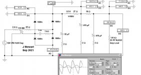
Now we wait to see how it sounds in real life. I'm especially curious about that R17 33R resistor. That's a sort of harmonic equalizer. In simulation it reduces 3rd harmonic by quite a bit, but that's into a virtual, resistive load. How will it act driving a real-life loudspeaker with wiggly impedance curve? Remains to be seen (heard).
My experience with simulated designs is that the basic stuff comes out really, really close. DC voltages, frequency response, gain, all usually are predictable. THD, sound quality and how crazy things like inductors and transformers act are far less predictable. Fortunately, you can switch to a more traditional biasing scheme simply by shorting out R17 to ground and replacing R10 and R20 with 560R instead of 510R. (You might want to leave room in your layout to allow doing that easily.)
Ever onward and upward!
I'm sure the amp will look really nice.
Now we wait to see how it sounds in real life. I'm especially curious about that R17 33R resistor. That's a sort of harmonic equalizer. In simulation it reduces 3rd harmonic by quite a bit, but that's into a virtual, resistive load. How will it act driving a real-life loudspeaker with wiggly impedance curve? Remains to be seen (heard).
My experience with simulated designs is that the basic stuff comes out really, really close. DC voltages, frequency response, gain, all usually are predictable. THD, sound quality and how crazy things like inductors and transformers act are far less predictable. Fortunately, you can switch to a more traditional biasing scheme simply by shorting out R17 to ground and replacing R10 and R20 with 560R instead of 510R. (You might want to leave room in your layout to allow doing that easily.)
Ever onward and upward!
I'm especially curious about that R17 33R resistor. That's a sort of harmonic equalizer. In simulation it reduces 3rd harmonic by quite a bit, but that's into a virtual, resistive load. How will it act driving a real-life loudspeaker with wiggly impedance curve?
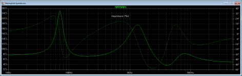
Some time ago I stumbled across an old Stereophile Magazine article that contained a model of a typical 2-way loudspeaker made up of real-world resistors, capacitors, and inductors. The magazine used this simulated speaker in their amplifier tests, in addition to testing with the usual 8-ohm resistive load. Here is a link to that article:
Real-Life Measurements | Stereophile.com
I created a SPICE model from this schematic and a companion speaker symbol. I generally run simulations using this model after I'm satisfied with the results using a pure resistive load. Attached is a ZIP file containing both the symbol and the SUBCKT model file. I've also attached a plot of the simulated speaker's impedance.
Maybe someone else will find this useful.
Attachments
Last edited:
Thanks, rongon.
I've had experience with these designs working out and being a painful experience. I'll just have to assemble, test and see what happens. I'm sure I can adjust as needed.
Unfortunately, the CNC shop told me that my design for the wood base was not suitable for CNC, which sounds more like 'we don't want to do this'. I have .dwg and .dxf files so I' sure I can shop around. Any CNC shops out there anyone would recommend?
Kofi
- Home
- Amplifiers
- Tubes / Valves
- 6L6GC UL PP Fun Time!