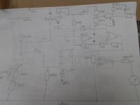
I've used the attached circuit with no issue's. All R's are 10k except R13 which is a 100k, I used a 10T preset. I used a TL074, one opamp configured as a buffer with a 10M IP resistor so as not to load the previous stage, EG IP taken from V1/gain stage anode via a coupling cap, as shown in the other schematic, which is included to give a rough idea of implementation only, not shown is the 10M from non inverting IP to ground. Ignor the diodes on the IP, no idea what I was thinking there.
The circuit as mentioned consists of a buffer, precision rectifier and buffer/meter driver. The 360r resistor prior to the meter is what I found to be right for my meters,it might need changing for yours. Your circuit might be different,but comparing the two might reveal what's going wrong. The VU driver attached fliks the meter over to FSD on power up,then settles.
Andy.