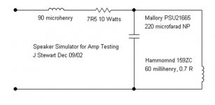
Some time ago I stumbled across an old Stereophile Magazine article that contained a model of a typical 2-way loudspeaker made up of real-world resistors, capacitors, and inductors. The magazine used this simulated speaker in their amplifier tests, in addition to testing with the usual 8-ohm resistive load. Here is a link to that article:
Real-Life Measurements | Stereophile.com
I created a SPICE model from this schematic and a companion speaker symbol. I generally run simulations using this model after I'm satisfied with the results using a pure resistive load. Attached is a ZIP file containing both the symbol and the SUBCKT model file. Maybe someone else will find this useful.
This looks cool. I will be using this. Great post. Thanks, Ray.
Kofi
Speaker Simulator
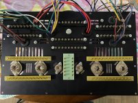
Here is mine in hardware. Used now almost 20 yrs.
I found Stereophile Magazine rather blue Sky, BBBS. Don't ask!😀
Not very technical, seemed under the very strong influence of those who bought space for their products. My opinion.
The speaker simulator schematic copied from Stereophile(?) mag has been doing the rounds for a very long time, I've used it in the odd simulation just as others have.
But the real thing rules!
Attachments
There is always more than one way to skin a cat. Although the magazine itself might have had its biases and influences like any other magazine, the speaker model originated with Jensen, a reputable speaker manufacturer. I see no reason not to consider it one of many possible representations of a real-world speaker since it too was constructed with actual hardware. What exactly is wrong with it?
This looks cool. I will be using this. Great post. Thanks, Ray.
Here is a library of speaker models that I came across a long time ago. I usually note the source of the models I use but I neglected to do so this time. But the models were provided by their manufacturers.
The subcircuits in this library are compatible with the speaker symbol I provided earlier. To the manufacturer's models, I added pure resistive models (Speaker-8ohm, etc.) so that I could use the symbol with both resistors and speaker models. The Stereophile model is the default, with the subcircuit name "Speaker."
Enjoy (or not!). 🙂
Attachments
A 220u cap! Strike a light! Isn't that a way too much? I might be missing something here but all capacitive load tests I've done use 2u at most and then certainly not at 0dB/full power OP.Here is mine in hardware
Andy.
Diabolical Artificer,
If you are referring to the 220uF in the schematic in Post # 62, then consider these approximations . . .
220uF is in parallel with 60uH, that is resonant at 43.8Hz, just like a woofer in a closed box.
And that is in series with 90uH (woofer voice coil inductance), and 7.5 Ohms (woofer voice coil DCR).
Did I get it right?
Y?
N?
schamatic hierarchical transformer model
Kofi Annan,
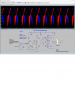
Here is a Ltspice schematic of your amplifier using my transformer model.
I had to change a few things (Ayumi, swap grids) to make it work for me.
You can use this model for all PP transformers. Just dial in the right numbers.
Enjoy.
Kofi Annan,
Here is a Ltspice schematic of your amplifier using my transformer model.
I had to change a few things (Ayumi, swap grids) to make it work for me.
You can use this model for all PP transformers. Just dial in the right numbers.
Enjoy.
Attachments
Unfortunately, the CNC shop told me that my design for the wood base was not suitable for CNC, which sounds more like 'we don't want to do this'. I have .dwg and .dxf files so I' sure I can shop around. Any CNC shops out there anyone would recommend?
Kofi
Internal square corners are tough to produce on a CNC router. What you have drawn up would be easier to produce by a finish carpenter.
Internal square corners are tough to produce on a CNC router. What you have drawn up would be easier to produce by a finish carpenter.
Yep-- that's what the CNC guy said. I wonder if I could just round all the corners in the drawing to a specific radius that would suit the router bits and have it done that way. Think that would work?
Kofi
That would work. Put a 1/8" radius on the inside corners and a 1/8" radius on your sheet metal to match.
This is all very interesting, I'm quite impressed with the results. I have built an amp based on the Heico HF89, but with 6L6, after simulating it (went the wrong way, built it then simulate it) I do not get near 0.1% THD at 20W RMS. Best I have got is around ~0.4%
I'm using Hammond transformer models generated from a spreadsheet (Robert McLean's Transformer Models Rev4.xls). When I replaced the 1650H model in "Simple 6L6GC Hierarchical.asc" the circuite became unstable. Using the original model works perfectly. Is the model I'm using not accurate enough or the original one is too optimistic?
Attached the 1650H model I'm using.
Attachments
This is all very interesting, I'm quite impressed with the results. I have built an amp based on the Heico HF89, but with 6L6, after simulating it (went the wrong way, built it then simulate it) I do not get near 0.1% THD at 20W RMS. Best I have got is around ~0.4%
I'm using Hammond transformer models generated from a spreadsheet (Robert McLean's Transformer Models Rev4.xls). When I replaced the 1650H model in "Simple 6L6GC Hierarchical.asc" the circuite became unstable. Using the original model works perfectly. Is the model I'm using not accurate enough or the original one is too optimistic?
Attached the 1650H model I'm using.
Looking at the .txt file, I'm wondering if you are missing an LP parameter for P1?
Not sure if I'm seeing this correctly, but heres' what I'm seeing. I think P1 may be missing?
LP1 1 Sg1 3.19344114792738
LS1 2 B 1.41930717685661
LS2 3 Sg2 1.41930717685661
LP2 4 P2 3.19344114792738
LA1 5 O8 0.00741645776380232
LA2 6 O4 0.00370822888190116
LA3 7 Com 0.02161314180004
KALL LP1 LS1 LS2 LP2 LA1 LA2 LA3 0.998434750532355
RP1 P1 1 30
RP2 Sg1 2 15
RP3 B 3 15
RP4 Sg2 4 30
RS1 O16 5 0.1
RS2 O8 6 0.1
RS3 O4 7 0.1
.ENDS Ham1650H
I enterred 1pF for Cp and Cs because there was no capacitance in the original schematic. So Kofi Annan's and my model are a bit optimistic.
In the model you use is probably some capacitance hidden. If You set Cp in my model to the same value it will likely oscillate to.
In the model you use is probably some capacitance hidden. If You set Cp in my model to the same value it will likely oscillate to.
Not sure if I'm seeing this correctly, but heres' what I'm seeing. I think P1 may be missing?
LP1 1 Sg1 3.19344114792738
LS1 2 B 1.41930717685661
LS2 3 Sg2 1.41930717685661
LP2 4 P2 3.19344114792738
LA1 5 O8 0.00741645776380232
LA2 6 O4 0.00370822888190116
LA3 7 Com 0.02161314180004
KALL LP1 LS1 LS2 LP2 LA1 LA2 LA3 0.998434750532355
RP1 P1 1 30
RP2 Sg1 2 15
RP3 B 3 15
RP4 Sg2 4 30
RS1 O16 5 0.1
RS2 O8 6 0.1
RS3 O4 7 0.1
.ENDS Ham1650H
No, it's there. Attached is the schematic of Robert's model with all of the implied nodes identified. The winding at P1 is modeled with Rp1 between nodes P1 and 1, and Lp1 between nodes 1 and Sg1
Attachments

The biggest difference between the transformer models is the K-factor.
If you put the K-factor from Kofi Annan in 1650H.txt
i.e. KALL LP1 LS1 LS2 LP2 LA1 LA2 LA3 0.9996 (was 0.9984)
The circuit simulates correct.
I don't know which factor is the right one for the 1650H. You have to measure the transformer and match the model to your measurements.
A lower K and/or adding Cp/Cs makes the transformer worse, and thus more difficult to stabilize the complete amplifier.
Last edited:
There is always more than one way to skin a cat. Although the magazine itself might have had its biases and influences like any other magazine, the speaker model originated with Jensen, a reputable speaker manufacturer. I see no reason not to consider it one of many possible representations of a real-world speaker since it too was constructed with actual hardware. What exactly is wrong with it?
OK for all using it in their Sims as I too have done. But mine is real in hdwr, on the bench & often used on real amplifiers. What's wrong with that?😀
There is nothing wrong with that, of course. But the model published in the Stereophile article is also a real construction using real resistors, capacitors, and inductors -- it's not just a SPICE model. This is probably where we are mis-communicating.
I have used a physical construction of this "speaker simulator" in amplifier bench tests. It's just a different model than the one you are using. So I think we are in general agreement that testing with a load resembling a speaker is a good thing, and that was in fact the basic premise of the Stereophile article -- real-world testing.
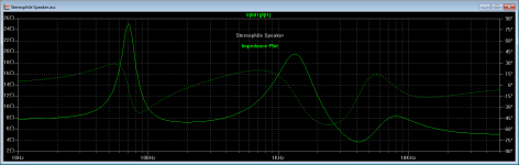
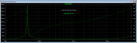
I've created a SPICE model for your circuit and have added it to my speaker library. I've also run a simulation of both models to plot their impedance over the audio band and have attached those plots here. They are quite different, so it's up to the user to decide which one they think is better for their own purposes. That's really what DIY is all about.
I have used a physical construction of this "speaker simulator" in amplifier bench tests. It's just a different model than the one you are using. So I think we are in general agreement that testing with a load resembling a speaker is a good thing, and that was in fact the basic premise of the Stereophile article -- real-world testing.
I've created a SPICE model for your circuit and have added it to my speaker library. I've also run a simulation of both models to plot their impedance over the audio band and have attached those plots here. They are quite different, so it's up to the user to decide which one they think is better for their own purposes. That's really what DIY is all about.
Attachments
- Home
- Amplifiers
- Tubes / Valves
- 6L6GC UL PP Fun Time!