Is crosstalk an issue with tubes? Could one 12AX7/AU7 combo be used for a stereo amplifier or would the soundstage be destroyed?
I guess preamp tubes are cheap enough to just use one half, but it seems like a waste.
I guess preamp tubes are cheap enough to just use one half, but it seems like a waste.
Careful Design
Poor performance in amateur built amplifiers can be often traced to the driver stage(s) rather than the power stage. Circuit simulators are a way to get an idea of whether a circuit is viable or not. The indications of distortion by the simulator don't mean much, the simulator assumes perfect devices. So while using real tubes & so on the wise experimenter bench tests performance of the various parts of the circuit before the soldered to the chassis stage.
When I built these amplifiers we all were using slide rules & pencil & paper. Just one of the reasons why I chose a paralleled 12AU7 as the driver & a 6AU6 to get enough voltage gain. Better attend to the finer points while that is still practical. That way your amplifier will work without further refinement. Must have got that right, my pair of PP UL 6L6GC amps accumulated a total of 34 years of trouble free operation. And would run again today if powered up.🙂
Re driver stage, the beefier the better in order to drive the OP stage cleanly. A paralleled ECC82 sounds just the job.
Re power supply, get the best you can, IE if your circuit calcs say you'll need 150mA get a tfmr capable of at least 200mA. If PSU power total is 200VA get a 250/300VA toroid. It's also nice to have a taps on the HT winding so you can lower/increase HT/B+. With a non potted toroid with an extra few 10's of VA you can always add a few windings. Why the over specs? When you put the amp together it's nice to have the extra wiggle room and a rock steady supply with good regulation maketh the amp; it's what you listen to when push comes to shove.
Re power supply, get the best you can, IE if your circuit calcs say you'll need 150mA get a tfmr capable of at least 200mA. If PSU power total is 200VA get a 250/300VA toroid. It's also nice to have a taps on the HT winding so you can lower/increase HT/B+. With a non potted toroid with an extra few 10's of VA you can always add a few windings. Why the over specs? When you put the amp together it's nice to have the extra wiggle room and a rock steady supply with good regulation maketh the amp; it's what you listen to when push comes to shove.
Only problem with overspecifying the power transformer is heater voltages. Best to get it close IMO
Yes, it could take something like adding very small value series resistors to bring the heater voltage down to the safe operating area (</= 6.5V). Extra work, not desirable.
The best solution is to use separate power transformers for the plate supply and heater supply. That way the windings don't couple noise into each other. For instance, diode switching noise from the plate supply can appear on the AC heaters when the plate voltage and heater voltage are supplied by a single power transformer. That also allows you to choose your heater supply transformer to give you the right voltage on the secondary, while over-spec'ing the plate supply transformer to give you lots of current headroom.
The best solution is to use separate power transformers for the plate supply and heater supply. That way the windings don't couple noise into each other. For instance, diode switching noise from the plate supply can appear on the AC heaters when the plate voltage and heater voltage are supplied by a single power transformer. That also allows you to choose your heater supply transformer to give you the right voltage on the secondary, while over-spec'ing the plate supply transformer to give you lots of current headroom.
Hey hey!!
Finishing up the parts list for this and I'm wondering if I'm going to be able to find a suitable first capacitor. The ripple current is a lot higher than I'm used to (given the increase in current required by the supply) and PSUD is measuring about 1.5A of steady state ripple on the 12uF.
Any thoughts on this?
Kofi
Attachments
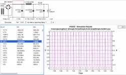
RMS current is what matters to the cap - scroll right and see what that is. Still may be a bit for a small cap - a larger value will increase voltage, but will have better regulation.
Thanks, Tom. It's a little over half an amp.
I should be able to parallel a couple to distribute the current, correct?
Kofi
I should be able to parallel a couple to distribute the current, correct?
Kofi
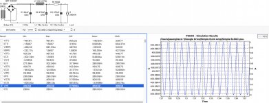
This should work better. Planning to parallel two 22uF (check them out here) and futz with the final resistor to dial in the voltage. Generally like to make a resistor-free PSU, but this may be the best option in this case.
Anything wrong with this approach?
Kofi
Anything wrong with this approach?
Kofi
Attachments
In PSUD2, try reducing the ESR of the capacitor from 2 ohms down to maybe 0.5 ohms. Does that reduce the ripple current by a lot?
Generally speaking, capacitors rated for high ripple current and 105 degrees C have lower equivalent series resistance (don't heat up as much). Low impedance/low ESR/high ripple current capacitors are more expensive, but it looks like this is a place where you'll want to use one.
Also, if you really only need 12uF, why not use a motor run polypropylene capacitor there? That type is designed for high ripple current situations and will have ESR much lower than 2 ohms. I bought a box full of 17.5uF 370VAC (approx 500VDC) that I'm not using. I'd happily send you a couple if you want to PM me with your shipping address.
DAYTON Motor Run Capacitor':' Oval, 370V AC, 17.5, 3 5'/'16 in Overall Ht - 2MDW1'|'2MDW1 - Grainger
Last edited:
Thanks so much for the offer, rongon! I thought about those too, but was worried about not having enough room in the chassis for them. How big are they?
Also, I did reduce the resistance and there was no material change the in the current across C1.
Kofi
Also, I did reduce the resistance and there was no material change the in the current across C1.
Kofi
This should work better. Planning to parallel two 22uF (check them out here) and futz with the final resistor to dial in the voltage. Generally like to make a resistor-free PSU, but this may be the best option in this case.
Why is a resistor-free PSU better? If that's the case, you have pretty much no choice but to either use larger chokes (which have unavoidable—and undesirable—resonances and higher DCR anyway), or regulated supplies.
Have you used PSUD2 to check for resonances in your proposed power supply? There's a good section about how to do that in Morgan Jones "Valve Amplifiers" 3rd Edition, which is available as a PDF here and there. Actually, if you don't have it, I highly recommend picking up a copy of either the 3rd or 4th editions. Jones' "Building Valve Amplifiers" is also excellent (less about design, more about construction and testing). So much valuable information in those books...
Also, when you parallel two capacitors, each capacitor's ESR is also wired parallel. As you know, two of the same value resistors in parallel = R/2. Your two 22uF caps with ESR = 2 ohms become a composite 44uF cap with ESR = 1 ohm. In PSU2, what happens if you change the internal resistance of that 44uF cap to 1 ohm?
Anything wrong with this approach?
Looks like a good compromise to me. And... Everything is a compromise.
--
Last edited:
How big are they?
Yeah, that's the downside. They're huge. 4" H x 3.5" W x 2" D.
Electrolytic caps are cheaper and much smaller (at the expense of higher ESR and shorter life).
Why is a resistor-free PSU better? If that's the case, you have pretty much no choice but to either use larger chokes (which have unavoidable—and undesirable—resonances and higher DCR anyway), or regulated supplies.
It's just been in my head based on a conversation I had on the forums many years ago about current sagging in a resistive supply. I'm probably over-rotating on it here.
Have you used PSUD2 to check for resonances in your proposed power supply? There's a good section about how to do that in Morgan Jones "Valve Amplifiers" 3rd Edition, which is available as a PDF here and there. Actually, if you don't have it, I highly recommend picking up a copy of either the 3rd or 4th editions. Jones' "Building Valve Amplifiers" is also excellent (less about design, more about construction and testing). So much valuable information in those books...
Also, when you parallel two capacitors, each capacitor's ESR is also wired parallel. As you know, two of the same value resistors in parallel = R/2. Your two 22uF caps with ESR = 2 ohms become a composite 44uF cap with ESR = 1 ohm. In PSU2, what happens if you change the internal resistance of that 44uF cap to 1 ohm?
Looks like a good compromise to me. And... Everything is a compromise.
--
Thanks again, rongon. I happen to have Valve Amplifiers in front of my on my desk at all times, so this was an easy reference.
Per Morgan's counsel, I created a 10X stepped load and looked for ringing across C2 and C3 and can't see any. Does this look correct?
Kofi
Attachments
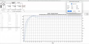
Yes, that's it. You might want to try varying the time set in the After... field. Also double-check that the transformer parameters are as close to real life as you can get them. That is key to getting a somewhat accurate simulation. But it all looks good to me.
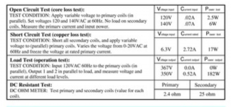
Oh... Is the power transformer's secondary winding DCR really only 26 ohms? That must be a big hunk of iron there...
Oh... Is the power transformer's secondary winding DCR really only 26 ohms? That must be a big hunk of iron there...
Been bouncing the 'after' times around and things look stable to me.
Also, I believe the DCR is correct for the transformer. I'm going to use a toroidal job from Antek to handle the current requirements and defray some cost.
I attached a (somehow blurry?) shot of the transformer specs. I think my simulation is correct?
Kofi
Also, I believe the DCR is correct for the transformer. I'm going to use a toroidal job from Antek to handle the current requirements and defray some cost.
I attached a (somehow blurry?) shot of the transformer specs. I think my simulation is correct?
Kofi
Attachments
Perhaps I'm missing something in this design, just reading from the start and skimming fast, but in the opening you felt that the driver would be adequate based on driving PPP EL84. Anytime you parallel those you get double the Gm so it's very easy to drive. On the other hand the Gm of a 6L6GC is half of that of an EL84, twice as hard to drive. So when I see you have only ~ 3.4v of biasing on the Cathodyne PI, which has less that 1 for gain, I don't see how you will get much drive to the finals without clipping at the PI stage. I'm assuming you will have near 20v of bias on the 6L6's? Yes?
Perhaps I'm missing something in this design, just reading from the start and skimming fast, but in the opening you felt that the driver would be adequate based on driving PPP EL84. Anytime you parallel those you get double the Gm so it's very easy to drive. On the other hand the Gm of a 6L6GC is half of that of an EL84, twice as hard to drive. So when I see you have only ~ 3.4v of biasing on the Cathodyne PI, which has less that 1 for gain, I don't see how you will get much drive to the finals without clipping at the PI stage. I'm assuming you will have near 20v of bias on the 6L6's? Yes?
I can certainly see what you mean here. I could definitely have used a more capable driver. I'm assuming something in the *SN7 family may be better.
Not sure if its worth the re-work necessarily but something for me to chew on for sure.
Kofi
There are several factors to consider in the compromise...
1) Paralleling output tubes increases the input capacitance of the output stage. To avoid slew rate limiting at very high audio frequencies, you want enough current sunk by the driving stage to charge the output stage input capacitance without 'losing steam' and turning sine waves into something like a triangle wave. It's not a huge problem, but it should be considered.
A plate current (Ip) of 3.4mA for the PI stage is probably adequate, but won't clip well when the output stage tries to go into class AB2 (one output tube in cutoff, the other drawing grid current). I don't think this design is aiming for class AB2 capability at all.
That doesn't answer how the amp is likely to behave with one output tube approaching cutoff and the other one not yet in grid current, which is a good question you raise.
2) Paralleling the output tubes does double plate current, double gm and halve plate resistance. I don't see how this equates to making the output stage easier to drive, though. The grid bias on the output tubes remains the same, so the audio signal peak voltage requirement remains the same (and as mentioned above, Cin has doubled).
EL84 usually has operating conditions where Vp and Vg2 = 300V and Vg1 = -12V.
Needing only 12V peak audio signal to reach full output is not a lot of signal swing from the preceding stage. That makes the EL84 quite easy to drive.
6L6GC often has operating conditions where Vp and Vg2 = 400V and Vg1 = -35V.
Paralleling 6L6GCs does not change the bias voltage if everything else (load impedance, etc.) is halved to compensate, so the paralleled 6L6GCs will still need 35V peak audio signal drive to reach full output. That's 3X more input signal than required by an EL84, so yes, 6L6GC is a more difficult load for any driver stage.
3) The cathodyne/split-load phase inverter stage is a follower operating under conditions of nearly 100% negative feedback. Its plate and cathode bounce up and down with the incoming (AC) signal voltage, so its DC bias should not shift until it runs out of supply voltage to swing.
Personally, I'd use a honkin' power triode as a cathodyne phase inverter. Something like a 5687, 12B4A, 6N6P, 6V6-triode, etc. However, I think a 12AU7 or 6SN7 should be quite adequate.
@Kofi - I'm sure you could rejigger the design from 12AT7 to 12AU7 with little effort. You might also consider 12AV7 (sort of a cheaper version of 5965).
There is a schematic out there of a PP 2A3 amp made with a 6V6 triode-wired and used as a cathodyne PI. I don't remember what the voltage amplifier stage tube was (sorry).
--
Last edited:
- Home
- Amplifiers
- Tubes / Valves
- 6L6GC UL PP Fun Time!