Read this thread:puginfo said:
i needed to understand the difference in this 2 types of secondary winding output HT Vac in the power trans.
1 - 0V-360V winding into a bridge 4 diode pack
2 - 360V-0V-360V winding into 2 diodes
im confused with both, they are full wave rectifiers but one has a center tap to form an earth. can someone clarify the benefits if any pls? thks
http://www.diyaudio.com/forums/showthread.php?s=&threadid=143095&highlight=
Pchw,
Following after the given thread, the advantage is simply a simpler transformer, less copper. During each half cycle with the 360-0-360 topology, there is always half a secondary sitting idle. OK, thinner wire could be used for the same heat generated, as each secondary work only half the time. But that would also mean a higher voltage drop than with double the thickness(area) of a single winding as for bridge topology.
Bridge topology came into fashion after "negative' rectification became simple with the use of semiconductor diodes. It was also possible with tube rectifiers, but at an expense and the need for three heater windings, as well as the extra vacuum rectifier voltage drop.
tubelab.com said:
It ain't me! I have a masters degree in engineering, but I never liked math. If it can't be done on the Windows Calculator, I don't use it. I got the highest grade in the class in DifEQ, but I flushed that buffer long ago.
I can and often do run simulations. Unfortunately many vacuum tube models are poor, especially pentodes. I trust the Tubecad P-P calculator, but it only works in triode mode. It correlates very well with my measurements on the 6L6GC in triode mode. I can probably cook up a simulation in LTspice, but I am leaving town in 2 days, so It will have to wait until I get back.
Hi,
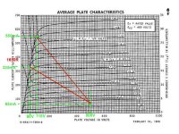
I've been playing with a pair of 807s and I thought the curves looked
familiar. Here is the chart posted earlier with 2 load lines, for 6600
plate-plate and 3300 plate-plate class B (or AB)
Solving for Po based on voltage, I get (311V RMS^2/1650 ohms) for
about 59 watts into 6600 ohms plate-plate, and (276V RMS^2/825)
ohms for about 92 watts into 3300 ohms plate-plate.
I'm calculating 160 mA average per tube at 6600 ohms and 236 mA
average per tube at 3300 ohms, based on
65mA idle + ((270 mA pk-idle)/2.83) for the 6600 ohm example
65mA idle + ((343 mA pk-idle)/2.83) for the 6600 ohm example
Does this make sense?
Michael
PS is 65mA per tube a bit high for class AB? It would extend the
class A region by quite a bit considering the 3300 ohm load line.
It looks like the 6600 ohm case doesn't get much into AB2 but
the 3300 ohm case could get 20-30 mA grid current peaks.
Attachments
Michael,
Thank you very much for your reply. It seems that you draw your load line directly from the operating point at a slope of 1/4 the primary impedance. The only thing that bothers me about this is that it seems that biasing colder or hotter has little effect on overall output power. I always thought that it was a given that colder bias would bring more power at the expense of distortion. That's why the more complicated method of drawing a class A load line and intersecting class B load line made sense to me. Was I wrong? I certainly can't explain George's results with that method.
Seriously, I am having trouble sleeping not being able to figure this out. Am I addicted to tubes?
Thank you for taking the time to respond.
With push pull tube amps, you have to think about what happens during the transition from one side to the other, just like the crossover region in Mosfet and bipolar sand-state amps. The more power you can deliver before having to make the transition from Class A to Class AB, the cleaner the low-level sounds will be.
This is the reason behind using heavier bias current, as the amount of peak power deliverable is determined by the voltage headroom for a given transformer turns ratio, the bottom plate voltage, and the peak current capabilities of the tubes at max drive level, not by the bias. You could run with little or no bias current in the tubes without affecting the max peak power, but it might sound like doo-doo.
The point of Class AB2 operation is being able to squeeze some more juice out of the tube by biasing the grid positive with respect to the cathode. This comes at the expense of having to deliver some current into the grid, as it will tend to intercept some of the electrons on their way to the plate - more and more so as the grid is biased more positive with respect to the cathode. Not all tube datasheets give curves for this mode of operation, so it may be difficult to predict what's happening without manually running the curves on the bench.
The bias level is really important in determining the output power for a single-ended amp, as it determines the maximum symmetric positive and negative swing you can handle before clipping (what goes up, must come down, and you can't go any lower than zero in an SE setup). With push-pull, the situation is different, as each side handles 1/2 of the signal swing, with one tube alternately handing the action while the other is idling/in cutoff.
SpreadSpectrum said:Michael,
Thank you very much for your reply. It seems that you draw your load line directly from the operating point at a slope of 1/4 the primary impedance. The only thing that bothers me about this is that it seems that biasing colder or hotter has little effect on overall output power. I always thought that it was a given that colder bias would bring more power at the expense of distortion. That's why the more complicated method of drawing a class A load line and intersecting class B load line made sense to me. Was I wrong? I certainly can't explain George's results with that method.
Seriously, I am having trouble sleeping not being able to figure this out. Am I addicted to tubes?
Thank you for taking the time to respond.
First, the shape of the load line is never a straight line anyway. My
avatar is a real-life load line of music playing on a SET with a loudspeaker load.
The load lines we draw on the plate curve chart are a highly
idealized thing that helps calculate the operating envelope of the
circuit. In the end it still results in a more or less linear transfer function
In this case, no matter how you get there, the end points of the
load line are as shown and the voltage, power delivered, etc. are
more or less the same as if we had taken the straight line path.
Maybe the power dissipated by the tubes is different, but the
transfer function is still more or less linear.
It's true in amp design that using a colder idle point sometimes
allows a load line with greater voltage excursion to be chosen for
more power out. It doesn't work the same the same to change
the idle current with an existing design. It does as wrenchone
says, increase the class A operating region.
Michael
Michael,
A very interesting graph in your avatar. I am however puzzled by the two sharp transistions there. How is that explained?
Nevertheless, my main reason for contributing here is to add a factor about 'the greater the common ground at cross-over (both tubes contributing), the longer time spent in class A mode, the lower the distortion'. Matters are a little more complex than that. One also needs to consider the change in amplifier output impedance in this region. Ideally, where both tubes are driving, the 'internal' generator impedance is halved. Crossing from this to the 'single tube only' region, gives a kink in the characteristics that increases high order harmonic distortion. (This is more apparent with transistors, where the change is usually more abrupt than with tubes.)
Ideally, the best quiescient condition is achieved where this change-over is most linear, i.e. where the depletion of one tube's contribution is complemented by the other's increased contribution. That can be optimised for each set of tubes, but is not necessarily as simple as spending as much time in class A as possible (by nature of maximum tube ratings). This is best achieved with the aid of a spectrum analiser, and with tubes can be a very 'shallow' situation, thus not always serious; nevertheless.
The graph is a scope photo with about 50-100 mS exposure time.
The attached pdf shows how frequencies around the poles of the
loudspeaker load have elliptical load lines and how the impedance
changes for example from 60Hz to 200Hz.
The music waveforms are complex combinations of many frequencies
and trace complex paths through the operating region of the tube.
The scope display is X-Y with anode voltage on X and anode current
on Y.
For selecting the region of overlap in class AB, I think I am on the
same page. Ideally the decrease in gm of one tube will be mirrored
by an increased in gm of the other tube, and the total gm would be
more or less constant. The tube driven into increasing conduction
would be just getting into the linear region as the other tube is cut
off (or thereabouts). It's easier to visualize this on pentode curves,
where they "bunch up" at the bottom of the chart. Another technique
is to map out the composite transfer function and line up the
"hockey stick" curves so they add up to zero error (straight line)
as in RDH4 pp. 589 Fig 13.47 showing class AB biased to the point
of minimum distortion.
Michael
Attachments
Well I hit the books and I think I understand a bit better now. It seems like the only way to make accurate predictions is to draw the composite load line which can then be used to produce an actual load line for one tube. Then as you said things aren't ideal when you connect an actual speaker. I purchased the tubecad p-p calculator to avoid having to draw those things by hand.
Thanks for all the help, gentlemen. George, I apologize for being such a pest.
Thanks for all the help, gentlemen. George, I apologize for being such a pest.
SpreadSpectrum said:I purchased the tubecad p-p calculator to avoid having to draw those things by hand.
Hey! I just did the same thing 😉
Have not had much time to look at it, but does it only do triode calculations, or can you see U/L and pentode too? Looks like a good tool to help me get my head around things and gross error check for mistakes.
Chris
For load line analysis, I found this website to be rather good:
http://www.turneraudio.com.au/loadmatch3-pp-triodes.htm
and
http://www.turneraudio.com.au/loadmatch4-pp-beamtetrodes.htm
http://www.turneraudio.com.au/loadmatch3-pp-triodes.htm
and
http://www.turneraudio.com.au/loadmatch4-pp-beamtetrodes.htm
Thanks for all the help, gentlemen. George, I apologize for being such a pest.
No problem. Someone needs to force me to think every once in a while. I went through the same exercise several years ago to convince myself that my measurements were real. I had previously devised a rather complex method of measuring the true impedance of an OPT. This exercise allowed me to realize that all I need to do was plug it into the wall outlet. I also made up some 10 to 1 voltage dividers so I can now scope the plate voltage at full power without blowing up my scope. They have already been used in the PP experiments thread.
I purchased the tubecad p-p calculator to avoid having to draw those things by hand......Hey! I just did the same thing.......but does it only do triode calculations, or can you see U/L and pentode too?
It only does triode mode and there is only a short list of tube choices. It does however do a good job within those limitations and even gets the power output prediction very close, even in the positive grid region (A2 or AB2).
I have used LT spice for simulating tube amps as well. It works in triode UL or pentode mode subject to the accuracy of the vacuum tube model being used. I have collected tube models from all over the internet and found some to be useful, some useless, most in between. Pentodes are much harder to model and are especially error prone when used in a manner that it was not intended like screen drive.
Somewhere I have a complete Simulation for the Simple SE in LT spice. I did it a few years ago. I don't remember if it was triode only of it worked in other modes. I can't see it now since I am using a laptop in a hotel room in Tennessee right now.
I also made up some 10 to 1 voltage dividers so I can now scope the plate voltage at full power without blowing up my scope.
I just ordered a CalTest 1600V 100X probe for $44. Don't know if you have seen those around the internet. I thought it would work well for that purpose.
Its occurs to me that my "Bazooka Joe" 6LR8 P-P amp is all set to be a class AB2 amp if I want it to be. Right now, it's configured with with a hybrid differential Jfet/triode input phase splitter stage, mosfet followers, and ultralinear outputs. I'm thinking of shifing connections around a bit to turn it into a pentode output stage to squeeze the last bit of power out. It's pretty easy to configure either way, as long as my bias circuit is forgiving (a change of zener away).
"Bazooka Joe" 6LR8 P-P
I did a little searching, but only came up with your "Mighty Mite" project. Wouldn't mind having a look at your 6LR8 PP schem. Did you post this project in a separate thread?
Thanks,
Jeff
wrenchone said:Its occurs to me that my "Bazooka Joe" 6LR8 P-P amp is all set to be a class AB2 amp if I want it to be.
I did a little searching, but only came up with your "Mighty Mite" project. Wouldn't mind having a look at your 6LR8 PP schem. Did you post this project in a separate thread?
Thanks,
Jeff
I just ordered a CalTest 1600V 100X probe for $44.
I have not heard of that one. The budget does not provide for $44 scope probes (I need 2) right now when I can get by with 6 20 cent resistors. Maybe later if things improve.
To George -
There is a seller on fleabay currently offering (2) pieces of X100 probe, 250 MHz, for ~$75, free shipping. I'm tempted, just to have the things floating around within reach. At home, I currently have a TPI 100X probe and a Tek P5100, both bought on the web at a steep, steep discount. The 5100 is rough and tough, but rather large. You also have to cob a suitable ground clip for it, as the stock clip it comes with has some monstrous set of jaws suitable for clamping on a piece of conduit, but not in any normal circuit. I usually cob up something using the grabber from a spare ground clip and a bit of heat shrink. The TPI probe is ok out of the box, but not quite as rugged - it also has a lower rating than the P5100. If I remember correctly, the P5100 is good to 1500V, and the TPI probe is only good to 1200. Any more voltage than that, and you need to graduate to the 1000X probe, which looks like some weird cattle insemination device, but works just swell.
To Vinylkid -
There is no circuit available currently for Bazooka Joe, as he is still sitting in my basement with the PC board 80% stuffed. I've pretty much proven the main concept behind the board with some breadboarding work for other projects - I just need to decide what kind of amp I want (fixed bias UL vs. fixed bias pentode), stuff the board accordingly, and get moving on chassis work. The amp will use a SMPS of my own design (currently sitting at work - the volts and amps are just fine, but I'm not entirely satisfied with the EMI plots), and Hammond 1620 output iron.
I sat down today with a pencil and a bit of paper and realized that I have somewhere between 12-15 projects (both sand and vacuum state) at various levels of completion. I think it's time to move some of these off the bench and into the living room, but I suspect that won't be happening any time soon, what with work and radio obligations eating most of my time for the near future. As these projects hit the bricks, I will post separate threads, or augment ones I have currently running.
For the Bazooka Joe, the major mechanical consideration is how to mount the board on the chassis. I was thinking of using a frame routed out of oak or brown bakelite to hide the wiring underneath. The chassis will be a Bud converta box with wood or bakelite side pieces.
tubelab.com said:
OK, there are three places in your circuit that need a negative voltage source. It is possible to derive them all from the same negative supply but I doubt that the bias tap on the power transformer will work.
First off the CCS in your schematic is shown as being connected to ground. Depending on the choice of input tube and bias points the CCS will only have a volt or two to work. Morgan Jones made this work using an LM124 and a 6J6 tube, but most CCS's need more voltage. My old favorite the IXYS 10M45 needs at least 15 volts to be happy redardless of what the data shees says. All semiconductors exhibit voltage variable capacitance effects which are reduced by raising the voltage. You need something between -15 and -450 volts if using a 10M45. Regulation is not important.
The mosfet source is connected through a resistor to a negative voltage source. This voltage must be more negative than the peak negative drive voltage. In reality you need quite a bit more voltage. You need enough voltage to assure cutoff of the output tube. I like to have enough voltage to assure continuous current through the mosfet as the tube approaches cuttoff. The mosfet can source plenty of current into the grid of the output tube for AB2 or instantaneous overload, however the source resistor and negative voltage source must discharge the miller capacitance of the output tube to recover from overload. This is not such a big deal on a pentode , but is a big problem on say an 811A. I would go for - 100 volts or more. Regulation is not important, but the supply should be clean.
The bias pot is connected to a negative voltage source. Again I like to be able to adjust the output tubes to cutoff when bringing up a new amp, so you need at least -45 volts here. It was stated previously that the bias supply must be regulated if the plate supply is regulated. In reality the plate supply is not important it is the screen supply that controls the current through a pentode. The screen and the plate are the same supply in UL or triode, so if this supply is regulated, the bias supply must be regulated. The entire supply does not need to be regulated, just the source for the bias pot. A zener or gas tube is sufficient.
Why can't you use the bias tap on the power transformer? The Hammond transformers only have the tap on one side of the center tap (one purple wire). This means that you would only get to use a half wave rectifier. Normally this is used to supply a few microamps to a bias pot, so a half wave rectifier is common. However the mosfet works best if fed a few milliamps, which may make getting a clean supply difficult from a half wave rectifier.
What would I recommend? Well I have built several PowerDrive test boards that have been used in 6L6 type amplifiers among others. You are also going to need a positive voltage source to feed the drain of the mosfet. The easiest way to get there is to use a small isolation transformer that has two 120 volt windings. Wire them in series to make a 120-0-120 volt winding. I use a bridge rectifier with the center tap grounded to make +150 and -150 volts in a manner similar to most solid state power amps. This feeds the mosfet its + and - supplies. It also feeds the negative voltage to the CCS on the input stage. I use a zener diode and a resistor to make -68 volts from the -150 volt source.
I like the LTP type of phase splitter. I tested it using several types of tubes when developing the Simple P-P. I found that the gain was barely adequate to drive a pair of EL84's. There was not enough gain to allow the use of negative feedback or triode connection. I have not tried the 7591 tube, but I am not sure that a single stage LTP will be enough if you ever want to try 6L6's or other tube types, and it won't be enough if you want to run 6L6's in triode, which is what I found to be my favorite choice to get about 20 watts.
I have been working on this driver on and off for a long time. There are several influences in my life right now that have killed much of my tube time lately. I have realized that I went through all of 2008 without completing a single amplifier. That won't happen in 2009. I can't say when the PC board will be completed, or if funds will be available to get a batch made, so don't wait on me. I have just finished laying out the first proto board. I made two of them and have started populating one of them.
I have already received a few emails asking questions. Its late here and I need to get up early tomorrow, but I will start another thread at my next opportunity to post progress, testing, photos, and yes, schematics.
I am hoping that someone will indulge my lack of experience here and help me out with some advice for the power supply requirements for this amp.
I have reviewed the great advice provided in the post above by tubelab. Thanks George!
Trouble with the advice regarding a 110 x 2 isolation transformer is that that it is not easy to find one here in Australia, as we have 240 volt supply. I have managed to find a Chinese R core transformer 0-55V x 2 with two 115 volt primaries that I can wire in parallel to give a -150-0-150+ power supply. I have been looking at the Tubelab SE at the tubelab site. As I was thinking MOSFET source followers, I was looking at the "power drive" pages previously, not the TubelabSE. What I have noticed with the TubelabSE power supply is that George manages to get all of the power requirements off the one power transformer.
Tubelab SE
The tap for the positive supply for the MOSFET follower is straight from the B+. The negative supply is derived from the primaries of the power transformer. As I have plenty of spare capacity in the power transformer, could I not do the same? I have a Hammond 300BX transformer, 800 VCT 250mA (Tubelab SE uses a 550 VCT). Perhaps I could use one secondary and the centre tap if the voltage is too high. This would save expense/space/weight issues. I guess for this to work, I would have to use a MOSFET with a voltage capacity of greater that the B+ plus B- supply (400+150=55 volts). The 2SK2700 Tubelab uses would work, but difficult for me to source. I have been looking, some options I have been considering are 2SK1119 and STP2NK90Z. would these be suitable replacements?
BTW, I am planning on sticking very closely to the tubelab suggested design as in his universal board here LTP Driver PDF post
A further question... The universal driver uses a -10 volt supply for the CCS in the tail of the LTP splitter. The power transformer I have has two spare 5VCT 1.2A taps. I was planning on joining these for 10V, rectified should give 13-14 volts. Could use this raw or use a doubler cct to give more voltage and then regulate to the -10 to -20 volts required. Am I on the right track here?
Once I get the power supply issued straight in my head I will draw up a schematic of the whole amp for comments/criticism.
Thanks guys!
Chris
- Status
- Not open for further replies.
- Home
- Amplifiers
- Tubes / Valves
- 6L6GC AB2 Amp