I've been thinking if a "lite" version of a differential pair driver/splitter for a 7591A P-P amp using the big triode in a pair of 6CS7s to cascode a set of matched JFETs (probably my old friends the PN4393). Tail current would be set at 10 mA or so, there will be a good bit of transconductance to throw around. Since I'll have a pair of minor-league triodes left over (not so minor, roughly equivalent to 1/2 6CG7 with slightly inferior transconductance), I was thinking of pressing them into service as cathode followers to buffer occasional dips into light AB2 operation without that nasty blocking feeling... Output iron would be a pair of transformers gutted from a Fisher 500B receiver (don't look at me that way, I didn't do it). I've done a preliminary version of the differential cascode circuit using the 4393s with a 12AU7 on top for cascodes. The results looked good. The big triodes in the 6CS7 would allow me to throw some more current around, yet keep a goodly amount of voltage at the JFET drains without any complex biasing scheme. I've been collecting 6CS7s for some time, and this finally looks like a logical application.
For a screen driven sweep tube service, the second set of triodes could be pressed into service as voltage amps to get more swing, and used to drive MOSFET followers to give the screens that big push they deserve.
For a screen driven sweep tube service, the second set of triodes could be pressed into service as voltage amps to get more swing, and used to drive MOSFET followers to give the screens that big push they deserve.
George, I can't quite figure out how you are getting that much power out of 6L6GCs as pentodes with a 6.6k a-a load. By my calculations you would get about 48 watts if you swung the plate to 0V from 500V at 60mA with zero transformer loss.
It seems like 6.6k would be too high to get those kinds of power outputs. Are you sure it is 6.6k? Am I missing something obvious?
It seems like 6.6k would be too high to get those kinds of power outputs. Are you sure it is 6.6k? Am I missing something obvious?
George, I can't quite figure out how you are getting that much power out of 6L6GCs as pentodes with a 6.6k a-a load.
If anyone has read the post that I just deleted ignore it. I am sure of my power measurements 75+ watts in pentode , and 45+ watts in triode. What I am not sure of at this moment is the exact load impedance. I have been using some OPT's that I am not sure of, so I am about to hook up a known one.
By my calculations you would get about 48 watts if you swung the plate to 0V from 500V at 60mA with zero transformer loss.
The Plate in an inductive loaded amp can approach twice the supply voltage.
OK the blonde moment is over, I understand what is going on. The David Lucas transformer has a whole bunch of odd colored wires. My previous measurements were taken with the 8 ohm load on the 16 ohm tap reflecting a 3300 ohm load to the tube. So SpreadSpectrum is correct a 6600 ohm load wont get there from here. It will do more than 48 watts for the reason stated in my previous post.
I decided to start over with the standard guitar amp transformer that I have been using for all of my P-P amp testing. I use these because I have a lot of them and I am not afraid of blowing them up, and yes I have caught one on fire! I have the Schumaker spec sheet showing that they are 6600 ohms CT with 4,8,16 ohm secondaries. They are rated for 80 guitar amp watts which are meaningless for Hifi. They will handle about 25 to 30 watts over the full audio range and sound quite nice at that level.
So I wired in one of these transformers in pentode mode and made some measurements:
VG2 - 400V VP - 500V Idle current set to 65 mA per tube.
3300 ohm load yields 91 watts @ 3% and draws 175 mA per tube
6600 ohm load yields 57 watts @3% and draws 110 mA per tube
13200 ohm load yields 29 watts @3% and draws 78 mA per tube
Triode mode VG2 = VP = 450V idle current 32 mA per tube
3300 ohm load yields 57 watts @ 3% and draws 145 mA per tube
6600 ohm load yields 41watts @3% and draws 95 mA per tube
13200 ohm load yields 25 watts @3% and draws 63 mA per tube
The Plate in an inductive loaded amp can approach twice the supply voltage.
Right. It should hit about 700 volts with both tubes working together (each tube seeing 3.3k) before it cuts off and the other tube takes over completely. I'm just looking at the downward (for plate voltage) travel to calculate plate current swing. See the attached load line. With 60mA bias current, total current swing (with plate hitting 0V) can be 303mA - 60mA or 243mA. P = (I^2)R or (.243/1.414)^2 * 1650 which is 48.73W. With a square wave this could be as much as .243^2 *1650 which would be 97.4W. Still, it seems like you were a lot closer to a sine wave than a square wave. This is discounting transformer losses as well
Looks like you posted while I was drawing my picture. I'll post it anyway just so others can see why I was scratching my head. 3.3k seems like a lot better load for getting max power. Positive grid voltage wouldn't even get you more power with 6.6k.
So what can we do to get more power in triode? Does it start to hard clip at about those points?
Be careful. Do these tubes have gold plated grids? My chinese coke bottle 6l6s look like they do.
Attachments
Do these tubes have gold plated grids? My chinese coke bottle 6l6s look like they do.
Don't know. I will find out when one finally blows up. It sat running at 50 watts in triode mode for nearly an hour last night while I watched Lost. The grid was touching +45 volts on peaks. Nothing bad happened. I don't think I want to put my EH KT88's in there though.
I do have a whole box (25 tubes) of new 15 year old Chinese KT88's that blow up for no reason, often violently. I will put some of them in just for fun when I have time.
It looks like I might get to leave work reasonably early tonight, so I think that it is time to try some sweep tubes!
tubelab.com said:
Triode mode VG2 = VP = 450V idle current 32 mA per tube
3300 ohm load yields 57 watts @ 3% and draws 145 mA per tube
6600 ohm load yields 41watts @3% and draws 95 mA per tube
13200 ohm load yields 25 watts @3% and draws 63 mA per tube
I lost one of my ECG 6BG6GA's last night. I have idle current set at 48ma per tube. VP is ~420V running triode. Is that too much idle current for these tubes?
Jeff
It will do more than 48 watts for the reason stated in my previous post.
I thought about it and I'm still not following...
I was calculating power by looking at the first 180 degrees of the sine wave(from the grid's perpective), so the fact that the plate can swing higher than 500 shouldn't matter. Well, it does matter in that it means that the load on the tube is 3300 while the opposite tube is still conducting(going up to 700V). This stops at 120mA and the tube load goes to 1650. The load line ends at 303mA(The plate can't go negative, can it?), which is the most current you can get out of any tube with a B+ of 500V and a load of 1650 in the class B region of operation regardless of the tube's characteristics. Since that's the most you can get, your max current delta is 243mA. P = Irms^2 * R which still gives about 49 Watts. See my load line above. Is my math wrong somewhere?
Maybe the load isn't 6.6k?
When I did my AB2 Triode KT88 experiments I got almost exactly what I calculated for max possible power for my B+ and idle current.
Don't know. I will find out when one finally blows up.
I just bought brand new ones from AES and the grid is visible through the plate structure. It sure looks like shiny gold to me. I guess it is possible that it is some other gold colored metal.
I lost one of my ECG 6BG6GA's last night. I have idle current set at 48ma per tube. VP is ~420V running triode. Is that too much idle current for these tubes?
Well, you are above screen voltage rating and slightly above power rating. Maybe this tube is not one of those that you can push real hard.
It will do more than 48 watts for the reason stated in my previous post.
OK, maybe there is one more non obvious thing. If the OPT was 6600 ohms. Each tube sees half of the primary winding which is 1650 ohms, not 3300 ohms, since the impedance ratio is the square of the turns ratio.
I was quite suprized to see 57 watts in triode mode with a 3300 ohm load so I simulated this in the Tubecad P-P amp calculator, which predicts 60 watts under the same conditions. It also predicts some serious 3rd harmonic distortion which I am not seeing.
It sure looks like shiny gold to me.
Mine look dull and grey, but these tubes must be at least 5 years old. Maybe they changed the recipie. I have a newer set somewhere, but they are at least 1 year old.
I did some screen drive experiments last night but it was too late to post the results. I managed to squeeze 125 watts from a pair of 6BQ6GTB's before I blew the screen grid out of one of them! More experiments tonight.
tubelab.com said:
I was quite suprized to see 57 watts in triode mode with a 3300 ohm load so I simulated this in the Tubecad P-P amp calculator, which predicts 60 watts under the same conditions. It also predicts some serious 3rd harmonic distortion which I am not seeing.
Wow, that is awesome!
How does it sound, compared to say your 300B Beast?
When can I buy some PC boards?
I may be guilty of repetition here, but I use 4 x 6L6GC in a parallel/p.p. AB1 output circuit, giving 120W out. (Anode Voltage = 560V, G2 voltage = 460V, fixed bias, Ia = 45mA per tube.)
Each tube sees half of the primary winding which is 1650 ohms, not 3300 ohms, since the impedance ratio is the square of the turns ratio.
That's what I used, 1650(except for when two tubes are working in parallel when both are conducting, then the load from one tube's point of view is 3300).
I was quite suprized to see 57 watts in triode mode with a 3300 ohm load
That seems totally reasonable to me. I got almost 50W out of Kt88 triodes with a 5k load. It seems to me that the triode's characteristics would be irrelevant here, just your ability to drive the grid and the tube's ability to stay alive. Of course, the tube's rp would determine overall Zout and linearity would determine distortion.
I'm having trouble understanding how you can get 57 watts in pentode at 500V with 60mA with a 6.6k load. I can't make that work with a load line that doesn't cross over into negative plate voltage. Also, load line is considerably below the knee of the curves here. 6.6k seems like a terrible load to extract much power out of 6l6s as pentodes. I don't know how you did it.
Power should just be a function of how far up the load line you can go. I'm pretty sure that in my KT88 experiments I got the plate to a lower voltage in triode than I could have as a pentode. There is just that point up the load line with a pentode that increasing grid voltage will not decrease plate voltage. No such problem with a triode, just other problems.
A thought here: Electrons won't want to migrate from a cathode at ground potential to a plate of negative potential, making it more negative will they? The grids will accelerate them that direction, but will they stick to the plate? I imagine not. I also imagine there would be monstrous grid and screen currents here that would destroy the tube. Maybe I should start a new thread so I can get this resolved in my mind without clobbering this one.
Well, the tube is being driven way beyond its specified limits such that the screen is operating as plate (and as George testifies, filament, too) so all bets are off, except that the tube's life is likely to be short and colorful (mostly red, and maybe some yellow at the final moments...).
So your theory is that red screening a pentode increases power output? I would think that a screen at 400V wouldn't send too many electrons to a plate at less than 100V even if it was red hot. I could be wrong. Anyway, I started a new thread so as to not hijack this one. Please straighten me out there.
New thread is here.
New thread is here.
Well, at 400 V on the screen, the plate is driven down close to 0V. George has shown this in his 6BQ6 screen drive experiments using far less drive voltage. If you have a low impedance screen driver, you can draw enough current from the screen to make it glow and run away.
Well, the tube is being driven way beyond its specified limits such that the screen is operating as plate
This is likely true in my screen drive experiments since there really isn't any published limits for screen driven audio amplifiers using sweep tubes. I have proven that it is possible to blow up the tube. The 6BQ6 in question still functions, it just doesn't work as well as it did before. I set it aside for now, but I will eventually break it to find out if I fried the grid or the cathode.
This thread is about 6L6GC's in conventional grid drive. I set the experiment up so that I was purposely staying within the specified limits of the tube. There is some published data on 6L6GC's in AB2 mode but this is all at a relatively low plate voltage, but it shows that positive grid operation and intended grid current is permissible with these tubes.
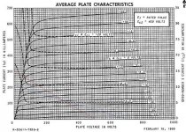
The 6L6GC is an improved version of the 6L6GB or GA and can be substituted for one. Most of us will now admit that the 807 is a repackaged 6L6GA or 6L6GB depending on when it was made, and all 807 specs apply to the 6L6GB EXCEPT for max plate voltage due to the octal versions propensity for arcing inside the base between pin 3 ans 2. So if we stay within the maximum plate voltage rating the 6L6GC can be used in 807 audio applications. Now lets look at the GE 807 data sheet under AB2 operating conditions. It is included below.
Under the column for 500 volts on the plate (only 300 on G2) you will find that they specify 75 watts of continuous (CCS) output with a 4240 ohm load. This is roughy half way between the 57 watts that I was getting with a 6600 ohm load and the 91 watts that I was getting with a 3300 ohm load. I was running 400 volts on G2 which requires a bit more bias, and allows more drive, but I believe that this may not increase the power much since going to 450 volts didn't help.
GE intended for the 807 to be capable of 75 watts with 500 volts on the plate, so there is no reason that the 6L6GC can't do the same with a similar load. Reducing the load to 6600 ohms and living with 57 watts makes life easier on the tubes. Conversely applying a 3300 ohm load and extracting 91 watts is harder on the tube, but the 6L6GC has a considerably higher plate dissipation rating than the 807.
I can not say where the load line example is wrong since the text is not readable here, except that it is a SE load line for a single tube. I went through a similar thought process a couple of years ago when I didn't believe my own numbers. I found an excel P-P load line drawing program on the web somewhere, but I can't find it now. I have also measured the peak plate voltage excursions (on sweep tubes) and found them in the 900 to 1KV range with my old 550 volt supply maxed out.
I realize that my power output numbers are out there, and I saw some unreal numbers last night, Almost 150 watts into that same 6600 ohm load. Granted the output WAS a square wave and I was torturing yet another sweep tube in screen drive with 650 volts on the plate (it is still alive). Since this is a thread about 6L6GC's, I started a new thread last night about my experiments. I was away all day today so I have not had time to post the results of a bunch of experiments. I thought up a simple way to verify the actual load impedance which I will perform now.
Results will be here:
http://www.diyaudio.com/forums/showthread.php?s=&threadid=143755
Attachments

Reducing the load to 6600 ohms and living with 57 watts makes life easier on the tubes.
Really? I always thought that putting a load line under the knee of the curves was bad for the screen as screen current rapidly rises there.
It is really not hard for me to believe large output powers for loads less than 4.5k. I draw the load lines and all comes out okay.
I can not say where the load line example is wrong since the text is not readable here, except that it is a SE load line for a single tube.
No. That is my attempt at a PP load line from one tube's point of view. For a readable version of the chart see GE 6L6GC data sheet.
My understanding of push pull load lines came from this post by Miles Prower, the first explanation that ever made sense to me.
Composite curves allow you to clearly view variations in composite rp and distortion, but they should not be necessary to do a simple max power out estimation.
Again, I am young, in my twenties, and I always assume that I am wrong when dealing with more experienced individuals such as yourself, but this shakes the very foundation of my understanding of push pull output stages, hence my desire to get this sorted out. It just surprises me that there isn't someone here who can just jump in and shower me with math.
I found an excel P-P load line drawing program on the web somewhere, but I can't find it now.
Steve Bench had one, the only problem is it is ridiculously tedious to enter tube curves into it. You have to do it point for point.
who can just jump in and shower me with math.
It ain't me! I have a masters degree in engineering, but I never liked math. If it can't be done on the Windows Calculator, I don't use it. I got the highest grade in the class in DifEQ, but I flushed that buffer long ago.
I can and often do run simulations. Unfortunately many vacuum tube models are poor, especially pentodes. I trust the Tubecad P-P calculator, but it only works in triode mode. It correlates very well with my measurements on the 6L6GC in triode mode. I can probably cook up a simulation in LTspice, but I am leaving town in 2 days, so It will have to wait until I get back.
tubelab.com said:
Your original proposal was for two monoblocks of 20 to 30 watts each. The original idea called for a power supply in the 375 to 450 volt range depending on the final choice of operating mode and circuit. This voltage requires a power transformer in the 325-0-325 to 360-0-360 volt range which as we all have found is hard to get.
i needed to understand the difference in this 2 types of secondary winding output HT Vac in the power trans.
1 - 0V-360V winding into a bridge 4 diode pack
2 - 360V-0V-360V winding into 2 diodes
im confused with both, they are full wave rectifiers but one has a center tap to form an earth. can someone clarify the benefits if any pls? thks
- Status
- Not open for further replies.
- Home
- Amplifiers
- Tubes / Valves
- 6L6GC AB2 Amp