Once again, thanks for the input George.
I am particularly interested in your comments regarding the 6SL7/6SN7. I have been wanting to do an all octal amp and having monoblocks should give me the chassis space to do this. Also like the idea of not having to fiddle around soldering on those small 9 pin sockets! The thought of a glowing VR tube on the top is still tempting too! Can I fit 6 tubes on each chassis...... 😉
I am particularly interested in your comments regarding the 6SL7/6SN7. I have been wanting to do an all octal amp and having monoblocks should give me the chassis space to do this. Also like the idea of not having to fiddle around soldering on those small 9 pin sockets! The thought of a glowing VR tube on the top is still tempting too! Can I fit 6 tubes on each chassis...... 😉
I have been wanting to do an all octal amp...I am particularly interested in your comments regarding the 6SL7/6SN7.
OK, crack open the Book of Morgan (third edition), turn to page 478 and study! The Crystal Palace amplifier is an excellent starting point. If you look at my schematic, and at Morgan's schematic you will find some differences, and some similarities.
The concepts are similar an LTP feeding another LTP feeding a pair of followers. The cascaded LTP's insure good balance even at the highest frequencies, and the followers can stuff all the grid current into the output tubes that they can eat. I don't know why, but to me this combination just sounds good too.
It is not practical to direct couple all three stages without some really complex stacked power supplies (except in some screen drive applications) so there must be at least one set of coupling caps in the audio path. Morgan chooses to place the caps between the first and second stages, I usually place them between the second stage and the followers. I do this to prevent any thermal or aging related drift in the second stage from affecting the DC bias in the output stage. This is more important with sensitive tubes like the 7591. In applications (screen drive again) requiring maximum output voltage swing I put the caps in both places.
I prefer to use a mosfet for my followers, Morgan uses 6J5's. For tubes in the 6L6 familly either should work well. Morgan uses an LM334 for the first CCS and a discrete transistor circuit for the second CCS. I use 10M45's for both. The LM334 works well with 2 or 3 volts but is only good to 10 mA and 30 volts. The 10M45 needs 20 volts or so to work but can eat 450 volts. I use it because it works well, and is a "one size fits all" chip. Use whatever you like, or can get in Australia.
Remember a 6J5 is one half of a 6SN7. 6SN7's should give more than enough gain here so that 6SL7's are not needed. If you go to 9 pin tubes a 6CG7 / 6FQ7 is very similar to a 6SN7.
Now, it's Saturday afternoon and for the first time in months I am not at work and have nothing better to do, so its time to "make em GLOW".
You the man! 😀
I hope that you have enjoyed your latest experiments! I have been following with interest and have "The Book of Jones" out on my desk.
As my job is a 'chauffeur de bus français' I will be in Singapore in a few days time and will be able to scrounge for parts. Two questions. First, Tubelab suggested (I think) a +/- 100 volt transformer supply for the mosfet source followers and for the bias. I am guessing that to set the bias, negligible current is required. Looking at 7591 data sheet, it is showing max signal screen current of 26.4mA for AB1 ultralinear. The 6L6 data sheet I have is showing about 20mA for AB1 tetrode, and 35mA AB2 (at 47 watts, way over my transformer spec). From memory, the small transformers I see up there are specified in VA. So, for around 26mA, I should conservatively have about 50mA? A 100-0-100 transformer would have to then be about 10VA?
Second question, as I will be shooting for a fully regulated B+ with maida style regulator, can I get away without a choke in the power supply? If not, I will scrounge for chokes as well...
Thanks everyone!
Chris
Eli Duttman said:Over on AA, Doug Piccard (Bandersnatch) asked for info. about the AcroSound TO-350 O/P trafo. IMO, that "iron" would stone cold KILL, when mated to 807s. 😀
Just look at this set of conditions obtained from TDSL.
Class Va Vg2 Vg1 Ia Ig2 Ra S Rk Zout Pout THD
AB2 P/P 600 300 -30.0 30-100 2.5-10.5 6,400 80.0 3.5
Regulated 300 VDC applied to the tertiary winding allows for full bore, maxed out, performance in UL mode. It seems that not much in the way of GNFB would be needed, to obtain both low distortion and good damping. 😎
I'm thinking of doing something pretty much identical to that, using Bogen DO-60 monoblocks... the OPTs in those have a pair of extra windings... taken together as a CT tertiary winding, it gives a good 25% UL winding. Not perfect UL ratio, but I should be able to get a pair of 6550/KT88s to make great power. About 620v on the plates, and maybe 350v on the screen windings. Even with the slightly mis-matched UL ratio, the inherent low distortion of the KT88 should out-perform the 807... at least in the IM distortion department, if nothing else.
I'm thinking about using the HK Citation II front end, with a 6SN7 cathode follower, direct-coupled to the grids of the output tubes... think of a Citation II front-end (driver/phase inverter) coupled to the Heathkit W7 back-end (cathode follower/output tubes/OPT). No sand here... but, I've got the example of the Heathkit W7, Ampeg SVT and other amps to give me good starting points on how to get the cathode follower working right...
Regards,
Gordon.
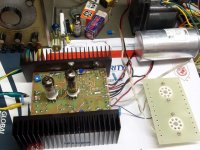
This was too easy, and rather anti-climatic. I wired up the 6L6GC P-P class AB2 power amp using the driver board I built yesterday. I have adjustable power supplies on everything so I set the knobs to what I remembered to be the max specs for an RCA 6L6GC, but there is no way I am going to put my black plate RCA's into something that has never been tested, NOPE, CHINESE. I got out my old friends the Chinese Coke bottles that have been seen glowing brightly on this forum before. The tubes were wired in pentode mode. 400 volts on G2, 500 volts on the plate 6600 ohm load. I set the current to 50 mA per tube (25 watts).
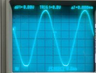
I started cranking up the audio generator. The power flowed freely. I cranked the generator up until the distortion meter read 2%. At 2% distortion the output power was 75 watts. OK, run it into clipping. 90 watts. Clean clipping, no ringing or funny stuff. Backing the power down to the 5% distortion point yielded 85 watts with visible clipping present.
I started cranking up the audio generator. The power flowed freely. I cranked the generator up until the distortion meter read 2%. At 2% distortion the output power was 75 watts. OK, run it into clipping. 90 watts. Clean clipping, no ringing or funny stuff. Backing the power down to the 5% distortion point yielded 85 watts with visible clipping present.
Attachments
I consulted the tube manual and found that the max screen grid spec in pentode mode is 450 volts, so I went there. It didn't help, in fact I think that I lost ground. The bias became touchy, power output didn't go up, so I shut it off.
I returned to 400 volts and played with the other knobs. I found that raising the bias current to 60mA per tube cleaned up the slight flatening that was visible on the bottom of the sine wave in the scope photo. Power at 2% improved to 80 watts, but the 5% level only went up to 87 watts. A full crank on the signal generator could make the analyzer read 104 watts but I am not sure how accurate it is when reading a square wave.
I also put the scope on the output tubes grid. The signal was swinging from -95 volts to +27 volts indicating the fact that the positive grid region was reached. We are well into AB2.
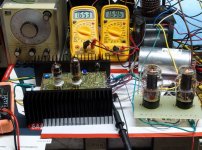
OK, I just had to take the obligatory picture with the lights turned off. We all want to see the glowing plates and melting grids, right?
Well, there aren't any. No GLOW, none, zip, nada, zilch! Maybe a little blue on the glass, but nothing in the red department. The red line seen in the picture is actually a reflection from the glowing heater. This thing ran at full power for at least 45 minutes, nothing got toasty except the load resistor.
I am sure that I could make red happen but the plate power supply I am using is capable of putting out 1.5 AMPS! It just eats tubes, and I would hate to kill these tubes they have served me well for 2 years, and I got them out of a Bandmaster that I retubed. I do have a box full of Chinese firecrackers (old KT88's) and some Penta EL34's, but that experiment will have to wait until I install a crummy OPT.
I have a self imposed rule of no high voltage experiments after 10PM especially when there is no one else at home, so all power is no shut off. I may have more time to tinker later in the week, or next weekend, but then I am away for 10 days, and I know that I will be behind again when I get back. I will try to draw up a schematic for what I am actually using, and then maybe some screen drive experiments.
I returned to 400 volts and played with the other knobs. I found that raising the bias current to 60mA per tube cleaned up the slight flatening that was visible on the bottom of the sine wave in the scope photo. Power at 2% improved to 80 watts, but the 5% level only went up to 87 watts. A full crank on the signal generator could make the analyzer read 104 watts but I am not sure how accurate it is when reading a square wave.
I also put the scope on the output tubes grid. The signal was swinging from -95 volts to +27 volts indicating the fact that the positive grid region was reached. We are well into AB2.
OK, I just had to take the obligatory picture with the lights turned off. We all want to see the glowing plates and melting grids, right?
Well, there aren't any. No GLOW, none, zip, nada, zilch! Maybe a little blue on the glass, but nothing in the red department. The red line seen in the picture is actually a reflection from the glowing heater. This thing ran at full power for at least 45 minutes, nothing got toasty except the load resistor.
I am sure that I could make red happen but the plate power supply I am using is capable of putting out 1.5 AMPS! It just eats tubes, and I would hate to kill these tubes they have served me well for 2 years, and I got them out of a Bandmaster that I retubed. I do have a box full of Chinese firecrackers (old KT88's) and some Penta EL34's, but that experiment will have to wait until I install a crummy OPT.
I have a self imposed rule of no high voltage experiments after 10PM especially when there is no one else at home, so all power is no shut off. I may have more time to tinker later in the week, or next weekend, but then I am away for 10 days, and I know that I will be behind again when I get back. I will try to draw up a schematic for what I am actually using, and then maybe some screen drive experiments.
Attachments

Which tubes did you use in the driver board in said experiment?
The input tube is a 12AT7 and the driver tube is a 6CG7. I started with a 5751 for the input tube and switched to a 12AT7 as an experiment. I don't remember it making much difference but I never got around to putting the 5751 back.
I noticed that the whole amp seemed to have plenty of gain, maybe too much, but I haven't tried connecting any feedback yet.
So not considering the driver stages, the output stage needs a power supply capable of 400V @ 120mA for this prototype?
The power supply that was feeding just the plates of the output tubes was set at 500 volts. Idle current was 120 mA. The current meter was reading about 300 mA at full power.
The 400 volt supply ran the driver board and the screen grids of the output tubes. The current was about 60 mA at idle and went to about 120 mA at full power.
The 400 volt supply ran the driver board and the screen grids of the output tubes. The current was about 60 mA at idle and went to about 120 mA at full power.
I was just thinking you are going to need a big power transformer!
Based on my previous "BFA" experiments I would guess that a single channel mono block could run on the Allied 6K7VG / Hammond 274BX transformer that I used in all of those "50 watt" guitar amps that I built years ago. The idle current is well within the rating of the transformer, but the peak current is over the transformer spec. The amp will see these kind of spec exceeding peaks for a small fraction of the total time so the transformer won't fry. Another very good choice is one of the large Antek toroids available on Ebay. Some of them could run this amp at full power for weeks without getting warm. I will likely build an amp based on these experiments at some point in the future since I have all of the parts. I will check into the power transformer selection at that time.
This amp was just a "warm up" experiment for a much bigger one to come. I bought two "400 watt" Plitron toroidal push pull OPT's from their "surplus page" two years ago for a very reasonable price. I will continue to experiment until I find a suitable fit for those transformers. This guy will need a big power transformer.
I designed the driver board such that it could be used for everything from the 6L6GC types used here to some monster sweep tubes. These experiments were just the first step in the testing and refinement of the driver. I would call this step a success even with my stupid moment with the PC board. The next step will involve some glowing sweep tubes!
Those are some serious heat sinks on that puppy. 
I was oogling at the Antek AN4T450 myself. 1A at 450v should just about cover it. I like that the voltage doesn't sag a lot on the toroids so the B+ shouldn't change a whole lot between idle and cranked.
I was oogling at the Antek AN4T450 myself. 1A at 450v should just about cover it. I like that the voltage doesn't sag a lot on the toroids so the B+ shouldn't change a whole lot between idle and cranked.
tubelab.com said:
Based on my previous "BFA" experiments I would guess that a single channel mono block could run on the Allied 6K7VG / Hammond 274BX transformer that I used in all of those "50 watt" guitar amps that I built years ago. The idle current is well within the rating of the transformer, but the peak current is over the transformer spec.
Hmmm. I have a pair of Hammond 278CX's...
Reckon one of them could run a stereo amp? 465ma secondaries, 400-0-400V... I'd think it'd probably be about right...
Also, with regards to the Plitron 400w monster outputs... George, have you tried any circlotrons or other zero-DC-on-the-OPT-primary designs yet? Seems like they'd be ideal for a toroid...
Regards,
Gordon.
Second question, as I will be shooting for a fully regulated B+ with maida style regulator, can I get away without a choke in the power supply? If not, I will scrounge for chokes as well...
My Maida has very little noise on the output. There is some noise (looks like bursts of damped high frequency oscillations at a rate of 120Hz) but it is very small. I am sure that these are from diode reverse recovery (using solid state diodes). I am pretty sure that I will be able to snub these out, but I haven't done that yet. I just barely pulled the power transformer out so that I could measure the leakage inductance and calculate correct values for the RC snubber.
Anyway, to answer your question, I don't think you need a choke but you may have to work a bit to make yours as noise-free as a choke would be. Remember that chokes have problems of their own that regulators do not, like voltage surges when the magnetic field collapses after initial cap charging, and extreme LF noise passes right through them. The choice is yours.
Those are some serious heat sinks on that puppy.
I got a whole box full of those heat sinks at a hamfest for $5 for all of them. They happened to have 4-40 tapped holes in the right places so I used them here. They are indeed serious overkill for this application, but as I found out no heat sink at all makes the 10M45 start smoking. They didn't blow however. I plan to use a piece of 1 inch angle aluminum screwed to the chassis for the heat sink in the final version. The big heat sinks are for the mosfets and CCS's in a monster SLCF output stage I have been planning.
I made a big F.U. when I did the PC board so the whole thing almost landed in the trash. After thinking about it for a while I made it live. Then I was in a hurry to see it work on Sunday so I got a little careless and tempted Murphy a bit, but he didn't visit. That story (short) is here:
http://www.diyaudio.com/forums/showthread.php?s=&threadid=143372
I have a 4T400 Antek and I recently got another one from Ebay that isn't on his web page yet. It is 4TK400. It has a 70 volt tap on each HV secondary which is good for the negative voltage supply. The down side that is perfectly UNCLEAR in the ebay ad is the fact that there is only ONE 6.3 volt 5 amp winding which isn't enough to feed a bunch of hungry sweep tubes. Both transformers together should have no problem supplying enough power for a multi gigawatt monster amp.
Ebay # 370192771510
The 4T400 made about 510 to 520 volts of B+ when feeding a Simple SE that draws about 200 mA. I am guessing it would be 490 to 500 with 2 channels of this amp.
When I build this amp I don't need to make 80 WPC. I currently have two possible scenarios, one is to use the "60 watt" David Lucas OPT's (made before he started ripping everyone off) that I used in this test, reduce the supply voltage to 450 to 480 volts and shoot for a 60 WPC amp. The other is to scale everything back even further to use some choice UTC LS57's that I have. How do I decide? I will test this driver board with 300B's and 307A's and every P-P OPT that I have, in search of a suitable replacement for my 300Beast amp. The leftovers get used on the 6L6GC amp.
George, have you tried any circlotrons or other zero-DC-on-the-OPT-primary designs yet?
Not exactly. I played with circlotrons a few years ago and lost interest. I may try again some time. I saw some impressive efficiency numbers in some of my previous screen drive experiments, but the output impedance is high requiring feedback. I saw some extremely low distortion figures and very low output impedance with cathode followers, but the drive voltage requirements are huge. I know that it is possible to make a cathode follower circlotron, and I don't see why it wouldn't be possible to do a screen drive circlotron, but these experiments will have to get in line behind the other ones that have been accumulating over the last year or so. I did do some testing when I first got the Plitrons and I was surprized at how sensitive they were to DC imbalances.
- Status
- Not open for further replies.
- Home
- Amplifiers
- Tubes / Valves
- 6L6GC AB2 Amp