tubelab.com said:
You can't do that. The 115 volt primary will not have enough inductance to run on 230 volts. It will draw too much current and usually leads to a rather smokey result. Someone told me this a long time ago when I wanted to use a 115 to 75 volt trasnformer in reverse to make 150 volts. I didn't believe them and I stunk up the whole house. The 2 X 55 volt windings can be used as is to make about + and - 75 volts which is enough for the 7591's but may be marginal for 6L6GC's or 6550's.
Thanks again for the advice tubelab, much appreciated. I guess I am showing everyone what a knucklehead I am! Like I said, I will be in Hong Kong in a week or so. I do know an area where they sell lots of different types of transformers. I will keep an eye out for something with dual 120 output. Failing that, as my approach above with doubling the voltage out of a dual 55 volt transformer by using 115 volt input rather than 230 volt input was poor, what about using the same transformers 2 x 55 volt output and putting it through a voltage doubler cct? The transformer is rated at 450mA, so should then be able to get about 100mA out of the + and - supply after doubling.
Sorry if I am wasting peoples time with stupid questions, I do appreciate the patience and guidance 🙂
Chris
Sorry if I am wasting peoples time with stupid questions, I do appreciate the patience and guidance
You are not wasting anyone's time, everyone is free to read, or not at their choosing. I have been asked these same questions many times, and have tried to answer them many times. I am capturing my responses in a text file for eventual use on my web site. I still can't seem to adequately explain the PowerDrive, and I know that explaining all of the possible configurations of the driver board will be harder than designing it. The "three different ways to kill a rectifier" text will definitely go on the web site!
I finally got to play some real music through my driver board and it sounds real nice....until you reach hard clipping. There is an oscillitory gremlin hiding inside somewhere that didn't show its ugly head with a resistive load. Loud music (Sherri is not home) through speakers makes it happen. I started a new thread to explore this.
what about using the same transformers 2 x 55 volt output and putting it through a voltage doubler cct?
This should work well. I am sure that your original plan to use an 0D3 will work too. I think that you may need a mosfet follower since the current through the 0D3 may exceed its rating before the other tubes warm up and begin to draw current.
I would be on the look out for a small transformer in HK that has four 115 volt windings, or a 5 or 6.3 volt secondary and two 115 volt primaries. You could even use two small transformers with 12 volt secondaries and 230 volt primaries. These are very common here, but may not be there. I don't know since I have never been there. I made one trip to Singapore but it was 1988, the world has changed a lot since then, but there were all sorts of goodies to be found in Peoples Park.
Thanks again for the input.
I now have a few options to chase up regarding transformers. I am sure one of them will work! Yes 230:12 volt transformers are available here, in Hong Kong and in Singapore so I will get something that works 😉 ...
Thinking about this option, small 240 to (low voltage) transformers are readily available here. In fact, there is a shop about a mile away that has these. I have plenty of current availability from the two 5VCT 1.2A secondaries and these transformers are quite small and cheap, saving space/weight/expense. Here is one example 240:6-15v 15VA Wired as you describe, two of these should be able to give voltages from about 80 to 190 AC.
MOSFET follower on the VR tube... I think this amp us going to have more sand than glass 😉
Thanks again for the help. Much appreciated!
Oh, BTW, yes, your post on killing a rectifier was very informative. I had read about conductance angle etc before, but you managed to put the ideas into words that made it all make sense in my head (and many others too I am sure!).
Thanks again!
Chris
So, after all of the help I thought I had better start drawing something up. I tried using image software in Mac (GIMP), but became frustrated at my lack of progress. I am having a hard enough time trying to get my head around some of the things the guys here have been helping with, let alone trying to learn how to use a drawing or cad program...
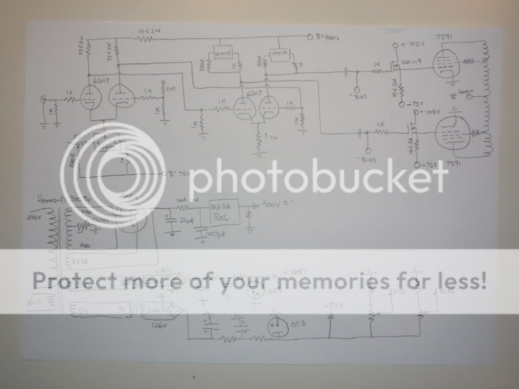
Hopefully this link to photobucket will work of a photo of a hand drawn schematic. It is unashamedly very much a copy of the great work done by Tubelab. Thanks for all the help George! I am sure tha I have made some errors and will still be after a bit of advice before cutting holes and slinging solder.
First question is what value resistor for the tail of the diff amp second stage? working out values for DC coupled stages is beyond me. If someone could even hit me with the basic concept I am happy to do the math.
Second question, tubelab mentioned a P-channel MOSFET pass device for the -ive supply. I have done some searching, but have come up trumps. I hate to ask so many questions as I like researching and discovering answers myself, but I feel like I am hitting the wall with progress.
I should be able to work out the current limiting resistors for the VR tubes myself OK. I know I don't need these VR tubes, but was hoping to do something a little different from my past projects.
BTW, the voltage figure given on the two transformers attached to the 5V secondaries of the Hammond power transformer notes to myself for the multi-taps on those transformers. I forgot to calculate x 1.4 for rectification... So actual values will be 96VAC from the +ive, rectified to 134VDC for the 0A3 and 80VAC rectified to 112VDC for the 0C3.
Once again, thanks for the ongoing help and encouragement!
Chris
The schematic - finally!
I have been working on this, trying to finalise the schematic. Have had difficulty trying to find a method to draft a schematic. The normal 'paint' type programs were to much of a PITA, and not that much around for Mac. There was a thread recommending some Mac schematic stuff, and I decided to give 'Designworks Lite' a try. Still having some trouble getting it to print reasonably, but I did a screen capture and turned it in to a PDF. Hope it attaches OK and is legible. Still a little tidying up to do, a few values still to sort out, but welcoming comments so far.
OH, at this stage, driver tubes are 6SN7 and outputs 7591 or 6L6 (will be switcheable in final). Missed value on second VR tube. Obviously it is a 0A3/VR75 for the -75V.
Things I am still uncertain about... Tubelab suggested that with the drive requirements I am after, I could direct couple the first LTP and the diff amp second stage. I have done that, but am a little unsure as to how to calculate the bias resistor in the tail of the diff amp (R9). I am not sure how to read the load lines for the first stage with the CCS with -75V. With 330R on the set pin of the 10M45 I know I will get about 9-10mA through the tail of the LTP, but not sure where the bias is with this setup. Not knowing this I am unsure what is going to the diff amp... Help....
Next little question, is it OK to put in a voltage divider reference to lift the 6.3 heater supply? Not sure if this is OK with the odd (for me) voltages hanging around the front end...
Last question, I am assuming that R22 with the input next to it (copied from tubelab's universal driver) is an input for global feedback? If not, where would an appropriate point be to inject this?
Cheers,
Chris
Attachments
I'm a complete nubie here - but shouldn't there be a couple of plate resistors on the output tubes? Other wise you have 400v to ground through the tube and nothing limiting the current...
I know I'm probably wrong for some reason - but I am curious as to how this works...
I know I'm probably wrong for some reason - but I am curious as to how this works...
I have done that, but am a little unsure as to how to calculate the bias resistor in the tail of the diff amp (R9).
There are two variables that control the value needed for R9. They interact, so I just played "musical resistors" until I got what I wanted. The input tube has a variable CCS in its tail. It sets the tube current. The input tube current and the plate load resistor value sets the plate voltage. I would build just the first stage and get it to work first. You are looking for low distortion with a reasonably low plate voltage. The two variables are the CCS current and the plate load resistor value. I shoot for a plate voltage near 100 volts, but 6SN7's tend to want more voltage.
The plate voltage sets the grid voltage for the second stage. You will chose the desired tube current for the second stage and set the CCS's up for that much current. I have my 6GC7 set at about 7 mA each side, and I would guess that a 6SN7 would want something similar. It can be measured by connecting a current meter from the plate pin to ground without the tube in the socket. You now know the tube current. The current through the cathode resistor is 2X the individual section current, and the voltage across the resistor is close to the negative supply value plus the plate voltage from the first stage. You can calculate an approximate resistor value from these numbers. The actual resistor value will set the plate voltage on the tube since the current is forced by the CCS. Tweak the cathode resistor to get good output signal swing.
The advantage to direct coupling the two stages is the elimination of capacitors from the signal path. The disadvantages are the loss of some drive voltage potential (not important here) and the possibilities of imbalance between the two sides due to tubes with unmatched sections. I have experimented with adding trimmer pots to allow for adjustments with varying success. Any offset adjustment added to the first stage to adjust a DC offset causes an AC gain imbalance. It might be a good idea to make the second stage CCS's adjustable (like the tail CCS in the first stage) to allow for adjusting the second stage.
R11 and R10 are not needed since the grids are directly coupled to the preceeding plates.
Yep, R22 is the input for GNFB. I added pads for a small cap across it in my latest board.
I still have my 2 X 6SN7 tag board driver. I can fire it up and try your circuit values, but Sherri has to go back up nort next week, so this weekend is pretty busy. I will have some serious circuit time next weekend though.
but shouldn't there be a couple of plate resistors on the output tubes? Other wise you have 400v to ground through the tube and nothing limiting the current...
Yes, there is nothing to limit the current. Any resistance in the plate circuit would also waste precious output power. The output tube current is controlled by the negative voltage applied to its grid. This can be derived two ways.
The Simple SE uses resistance in the cathode circuit to develop a positive voltage on the cathode while the grid is grounded. This results in a net negative potential between the grid and cathode. This is called cathode bias. It creates a DC "feedback" effect since a tube that wants to draw more current will develop a higher cathode voltage that tends to reduce this current. This allows different tubes to be used (within reason) without readjustment.
In this circuit the cathode is grounded and a negative voltage is applied directly to the output tube's grid. The advantage is that there is more voltage from the cathode to the plate allowing for more power. The disadvantage is that this "bias" voltage must be adjusted for each tube, and getting it wrong can fry a tube rather quickly. The bias must be readjusted every time the output tubes are changed, and after several hours of continuous use. This is called "fixed" bias. It isn't really "fixed", since you need to adjust it.
Since the negative grid voltage is needed to prevent tube meltdown, it is important to make sure that it is there before the output tubes are warmed up, and remains present whenever the amp is on. This is why some expensive amps have complicated circuitry to shut down the amp in the case of bias circuit failure.
Eli Duttman said:
The Tamura O/P trafos Chris is going to use provide a dedicated tertiary NFB winding. Taking OEM "hints" seriously is (IMO) sound policy. For a "classic" design that uses such "iron", look at the Marantz 8B.
BTW, the lowest fundamental a double bass can produce is approx. 31 Hz. IMO, a F3 of 19.5 Hz. presents little, if any, problem in the real music dept. Remember, the high pass pole is outside of the global NFB loop. 😀
Hi, Eli,
Can you please describe what did you mean "tertiary winding for cathode NFB"? I have looked at Tamura specification, they have winding for cathode NFB, 16Ohm impedance. Quite strange, I think it should be 7-10% or 25%.
Did you disassembled Tamura transformers for yourself?
Thanks.
As always George, thanks so much for taking the time to work through for me.
No rush on any testing. I want the build quality of this amp to be worthy of the design and components, so will be getting out the pencil and paper and working out some tag board designs and trying to use sketchup to make sure everything fits together properly before cutting holes in the nice chassis I have. Between work and other commitments, his will take at least a few weeks for me too I guess.
Attached is an updated pdf with the suggestions included...
LinuksGuru, the Tamura output transformers I will be using have a 16R "third winding" for NFB exclusive use. I think Eli was using the term 'tertiary' to describe 'third', ie primary=1, secondary=2, tertiary=3 etc... This winding is for global NFB, not cathode feedback, however.
Thanks again everyone!
Chris
Attachments
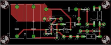
This is not required in most amplifier designs. It is a welcome addition in an amplifier design (like the Tubelab SE) where there are positive and negative supplies with resistive paths connecting them together. I ALWAYS design the negative supply to come up first (good for the tubes) but this can cause the positive supply to recieve a negative voltage before its rectifier tube is warm. This will be the case in the amplifier design discussed here.
I would be a fool not to add extra features to a board while I have the chance, especially when it doesn't make the board any bigger.
Here is the revised version:
Attachments
Thanks for taking the time to post your work here SpreadSpectrum. I know that I appreciate the effort and help.
As far as having boards made is concerned, what little investigation I have done has indicated that to make just two boards is quite expensive. I was going to use your board as a template to make one with wired connections on perf board. I don't know if you are interested, but have you thought of a group buy, or even if you are getting some done, would you be interested in spreading the cost a little by letting me in on your buy? I won't be offended if is to much hassle...
Once again, thanks for your assistance!
Cheers,
Chris
I was just about to suggest a group buy too...
It may be possible to get a inexpensive run of boards from Advanced Circuits ? They have a bare bones option that produces a minimal PCB.
It may be possible to get a inexpensive run of boards from Advanced Circuits ? They have a bare bones option that produces a minimal PCB.
I've used Advanced circuits several times, I try to stay away from them for boards that have more than two layers, since I've seen them come back with opens/shorts even with electrical test.
The nice part of using them is that you can submit your gerbers to freedfm.com and they will analyze your design and send you a report along with a quote. It's all automated so you can fix-resubmit-fix until you have a design that meets all their rules.
Also, their pricing (like most PCB vendors) is based on FR4 square inches so if you look carefully at the quote, you can maximize the number of boards you get for the same cost - until you roll over to a new panel.
An example would be a small board that I designed (CMOS sensor) that was a little more than 1" square. Buying 5 of them cost say $500, but buying 25 was only $600.
If you go this route, post the link you get for the quote, and I'll be happy to take a look.
Bare bones PCB from Advanced Circuits was going to be my first choice. Who needs a solder mask?
I wouldn't be opposed to adding some others onto my order to spread the cost around. Here's the catch: I am not going to have this board made. I am going to have a version made with two Maida regs on it. My amp needs five regulated voltages so I want to consolidate a bit. All boards in my amp are going to be 3"x 4" so that holes line up and boards can be stacked.
I am also making a digital volume control board based on DS1882 with BJT cascode current sinks for LTPs also on the board. Another one on deck is a microntroller power sequencer that also monitors cathode currents and shuts the amp down if output tubes draw excessive current. This board also includes a bias servo for maintaining output tube balance. USB DAC PCM2707 board in the works as well with optional TDA1543 output. Any of the other ones sound interesting? I'll be looking for a few partners with those as well to reduce costs. First I need to get the power supply smoothed out.
I would be willing to purchase 10 and sell off a couple to others. After 10 prices don't come down much. I've got 4 pre-school age kids so I don't have time for a huge group buy. Others are welcome to arrange a group buy with the single Maida board. I am not interested in using it myself.
Quantity of 10 at barebonespcb.com shows unit price of $9.60 for 3x4. Quantity of 1 is $47.40
Single Maida would be $44.88 for one and $7.08 apiece for 10. Not much of a savings.
Time for stupid questions again...
I am trying to teach myself the concepts as I progress with this, however, this is a slightly more advanced amp than most I have seen and tried to understand! I do like to try and research and learn concepts rather than just ask for answers, however I am stuck again. I am trying to get my head around what is going on with the LTP and diff amp input stage of this amp. I think I understand the basic concepts, but the CCS and direct coupling are complicating things to the point where I am having difficulty.
The driver designed by tubelab is a universal driver, designed to have the capability to drive many different loads. My task is to try to work out the components, operating points and values. It is this I am having the difficulty with.
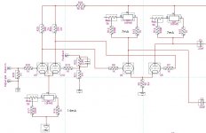
Problem 1. The LTP first input stage has a CCS on the tail. I understand that this makes the load line horizontal at the current set by the CCS over all plate voltages. I will be using 6SN7 for the LTP and diff amp second stage. From what I can gather 7mA is a good load for this tube. We now have to work out an operating point. The variables are plate voltage and bias. Plate voltage can be set by varying the value of the anode resistors knowing load (7mA+7mA) and using Ohm's law. This much I have worked out. Problem is, how do we know what the bias is for this first stage? There is -75V on the CCS and about +300V prior to the anode resistors. The cathode will need to be positive with respect to the grid, but how do I work out what this is? The only component is the 10M45 and it's adjustment resistor and stopper resistor. How many volts are dropped across this?
Problem 2. Working out points for the direct coupling. Tubelab said that “the voltage across the resistor [tail of the diff amp] is close to the negative supply value plus the plate voltage of the from the first stage.” Just to confirm, the negative supply value from the first stage plus the plate voltage from the first stage will be close to the voltage to drop across the diff amp cathode resistor. So for our example, if we have -75V supply to the first stage, and if the plate voltage was 150V, then the grid of the second stage would be +75V? We would then have to calculate for a cathode resistor that gave a voltage drop of 75V plus whatever bias was determined as required with the voltages available. So, using the numbers above (not yet assuming they are the best voltages to use), we would enter the 6SN7 plate curves along the 7mA load line and see that we have available voltage of 75V to supply voltage (less voltage dropped in CCS). So about 75V to 375V? The mid-voltage is 225V, so 225V on the 7mA line gives a bias of about -8V. So we would have to find a resistor that dropped 75V+8V (83V) at 14mA = 5928R, or 6K. Am I on the right track here?
Problem 3. Picking the best voltages for the two stages. My understanding is that this will be a compromise. Higher voltages on the first stage will allow better voltage swing here, but the higher the voltage here, the less voltage available at the second stage. As the input will be a standard CD player or pre-amp with 2V peak-to-peak, we only really need an anode voltage that will accommodate this? My thoughts are a plate voltage around 150V on the first stage, giving the figures above for the second.
Problem 4. Question is, how much voltage gain is required for each stage. I assume that will be determined by the drive requirements of the output tubes and how much negative feedback is appropriate. 7591 U/L requires about 41V peak to peak. I would like to be able to drive 6L6 in triode too. That will require somewhat more voltage, probably around 70V peak to peak I am guessing. I am also guessing that up to about 12dB of feedback would be appropriate. This is about 4 times voltage? So for 70V peak-to-peak out from 2V peak-to-peak input (0.707V RMS) I would need an amplification factor of 35. 12dB of feedback turns this in to 4 x 35 = 140. With a Mu of 20, the 6SN7 would give 10 in the LTP and 20 in the diff amp? Giving 200? Therefore the gain stages are adequate?
A gentle prod in the right direction if I have gone off the rails above would be great (and an explanation of how the bias works with CCS in the tail of LTP in this cct also).
Attached is pic of input stage with some best-guess values based on above.
Regards,
Chris
I am trying to teach myself the concepts as I progress with this, however, this is a slightly more advanced amp than most I have seen and tried to understand! I do like to try and research and learn concepts rather than just ask for answers, however I am stuck again. I am trying to get my head around what is going on with the LTP and diff amp input stage of this amp. I think I understand the basic concepts, but the CCS and direct coupling are complicating things to the point where I am having difficulty.
The driver designed by tubelab is a universal driver, designed to have the capability to drive many different loads. My task is to try to work out the components, operating points and values. It is this I am having the difficulty with.
Problem 1. The LTP first input stage has a CCS on the tail. I understand that this makes the load line horizontal at the current set by the CCS over all plate voltages. I will be using 6SN7 for the LTP and diff amp second stage. From what I can gather 7mA is a good load for this tube. We now have to work out an operating point. The variables are plate voltage and bias. Plate voltage can be set by varying the value of the anode resistors knowing load (7mA+7mA) and using Ohm's law. This much I have worked out. Problem is, how do we know what the bias is for this first stage? There is -75V on the CCS and about +300V prior to the anode resistors. The cathode will need to be positive with respect to the grid, but how do I work out what this is? The only component is the 10M45 and it's adjustment resistor and stopper resistor. How many volts are dropped across this?
Problem 2. Working out points for the direct coupling. Tubelab said that “the voltage across the resistor [tail of the diff amp] is close to the negative supply value plus the plate voltage of the from the first stage.” Just to confirm, the negative supply value from the first stage plus the plate voltage from the first stage will be close to the voltage to drop across the diff amp cathode resistor. So for our example, if we have -75V supply to the first stage, and if the plate voltage was 150V, then the grid of the second stage would be +75V? We would then have to calculate for a cathode resistor that gave a voltage drop of 75V plus whatever bias was determined as required with the voltages available. So, using the numbers above (not yet assuming they are the best voltages to use), we would enter the 6SN7 plate curves along the 7mA load line and see that we have available voltage of 75V to supply voltage (less voltage dropped in CCS). So about 75V to 375V? The mid-voltage is 225V, so 225V on the 7mA line gives a bias of about -8V. So we would have to find a resistor that dropped 75V+8V (83V) at 14mA = 5928R, or 6K. Am I on the right track here?
Problem 3. Picking the best voltages for the two stages. My understanding is that this will be a compromise. Higher voltages on the first stage will allow better voltage swing here, but the higher the voltage here, the less voltage available at the second stage. As the input will be a standard CD player or pre-amp with 2V peak-to-peak, we only really need an anode voltage that will accommodate this? My thoughts are a plate voltage around 150V on the first stage, giving the figures above for the second.
Problem 4. Question is, how much voltage gain is required for each stage. I assume that will be determined by the drive requirements of the output tubes and how much negative feedback is appropriate. 7591 U/L requires about 41V peak to peak. I would like to be able to drive 6L6 in triode too. That will require somewhat more voltage, probably around 70V peak to peak I am guessing. I am also guessing that up to about 12dB of feedback would be appropriate. This is about 4 times voltage? So for 70V peak-to-peak out from 2V peak-to-peak input (0.707V RMS) I would need an amplification factor of 35. 12dB of feedback turns this in to 4 x 35 = 140. With a Mu of 20, the 6SN7 would give 10 in the LTP and 20 in the diff amp? Giving 200? Therefore the gain stages are adequate?
A gentle prod in the right direction if I have gone off the rails above would be great (and an explanation of how the bias works with CCS in the tail of LTP in this cct also).
Attached is pic of input stage with some best-guess values based on above.
Regards,
Chris
Attachments
SpreadSpectrum said:Bare bones PCB from Advanced Circuits was going to be my first choice. Who needs a solder mask?
.
freedfm, 4pcb, barebonespcb... its all the same company. You can make a "barebones" pcb easy enough through freedfm...
If you are going to go through the trouble of building a PCB, I'd get the soldermask, it stops the copper from corroding and the solder from sticking where you don't want it too.
an explanation of how the bias works with CCS in the tail of LTP in this cct
The short answer is that the CCS pushes the cathode voltage up to whatever voltage it needs to be in order to get the current that it wants. This coincides with the correct grid bias voltage. If anode loads are equal and triodes are perfectly matched, anode voltages are equal. In practice, they work out fairly close.
If you are going to go through the trouble of building a PCB, I'd get the soldermask, it stops the copper from corroding and the solder from sticking where you don't want it too.
I'll just conformal coat when I am done and use flux liberally to make sure solder stays where it is supposed to. I'm a cheapskate.
SpreadSpectrum said:
I'll just conformal coat when I am done and use flux liberally to make sure solder stays where it is supposed to. I'm a cheapskate.
these days that is called "thrifty".
clearly you don't work in Government.
- Status
- Not open for further replies.
- Home
- Amplifiers
- Tubes / Valves
- 6L6GC AB2 Amp