You would probably be better of changing to a mu follower which has lower distortion and then add some Negative feedback to set the gain. Attached is a schematic of one I posted elsewhere in response to a similar question.
Cheers
Ian
Thanks Ian to share the schematic, my target is 25-30dBs seems that will need a lot of negative feedback😡
Cheers
Felipe
Thanks Ian to share the schematic, my target is 25-30dBs seems that will need a lot of negative feedback😡
Cheers
Felipe
For more gain you need LESS NFB. If you really want 25dB or so gain you could use a 6CG7 as a mu follower with no NFB. This gives very low distortion and approximately 26dB of gain.
Cheers
Ian
Hey guys,
I have plenty of ECC81, ECC82, ECC83 & ECC88 so I will try these:
1- SRPP ECC88 + cathode follower ECC82
2- SRPP ECC82 + cathode follower ECC82
3- Mu Follower ECC81
Advice will welcome
Thanks, Felipe
I have plenty of ECC81, ECC82, ECC83 & ECC88 so I will try these:
1- SRPP ECC88 + cathode follower ECC82
2- SRPP ECC82 + cathode follower ECC82
3- Mu Follower ECC81
Advice will welcome
Thanks, Felipe
I would use no cap at all, up the voltage close to 200V and change the output cap to 10uf @250V poly (dayton or solen is what I use)
I would use no cap at all, up the voltage close to 200V and change the output cap to 10uf @250V poly (dayton or solen is what I use)
For what topology? could you elaborate?
Hey guys,
I have plenty of ECC81, ECC82, ECC83 & ECC88 so I will try these:
1- SRPP ECC88 + cathode follower ECC82
2- SRPP ECC82 + cathode follower ECC82
3- Mu Follower ECC81
Advice will welcome
Thanks, Felipe
There is very little point adding a cathode follower to an SRPP. An SRPP already has excellent drive capability and a low output impedance. A cathode follower will have less output drive capability and about the same output impedance.
Cheers
Ian
A well-designed SRPP could have twice the output current drive capability of a similar cathode follower, but it will have a higher output impedance. This is because the upper valve is a modified CF with reduced buffering action, so the output load is to some extent 'visible' to the lower anode. This weakness is largely removed in the mu-follower, but then you lose the balanced drive of an appropriate SRPP. Swings and roundabouts!
A well-designed SRPP could have twice the output current drive capability of a similar cathode follower, but it will have a higher output impedance. This is because the upper valve is a modified CF with reduced buffering action, so the output load is to some extent 'visible' to the lower anode. This weakness is largely removed in the mu-follower, but then you lose the balanced drive of an appropriate SRPP. Swings and roundabouts!
In most cases the actual output impedance is immaterial since none of these topologies should be expected to drive a load anywhere close to its output impedance, not to mention the fact that 'output impedance' is really small signal output impedance and which is something else entirely when it comes to driving significant voltages into significant loads.
In my experience the SRPP output impedance is very similar and the drive capability greater than the mu follower (for a given tube) but the mu follower has the benefit of much lower distortion.
Cheers
Ian
Yes, with a mu-follower you are getting the bare mu-related linearity (or otherwise) of the lower valve because of the high impedance anode load. An SRPP might conceivably better this but only when balanced (most are not, as it requires exactly the right load impedance) and then only for even order distortion cancellation; odd order still adds.
Yes, with a mu-follower you are getting the bare mu-related linearity (or otherwise) of the lower valve because of the high impedance anode load. An SRPP might conceivably better this but only when balanced (most are not, as it requires exactly the right load impedance) and then only for even order distortion cancellation; odd order still adds.
Exactly. I have found an SRPP does well with some NFB applied. This lowers both the distortion and the output impedance which enhances the already good output drive capability.
Cheers
Ian
Exactly. I have found an SRPP does well with some NFB applied. This lowers both the distortion and the output impedance which enhances the already good output drive capability.
Cheers
Ian
Could you draw a schematic with how apply NFB to reach a gain 25-30
Cheers
Felipe
Use the circuit from post 60, but using ECC81 or ECC83 with suitable changes to resistor values.
Use the circuit from post 60, but using ECC81 or ECC83 with suitable changes to resistor values.
Post 60 isn't a mu-follower?
Last edited:
Post 60 is a mu-follower, with anode follower style negative feedback. You asked for a circuit which allows you to add negative feedback to achieve a gain of 25-30. That circuit, suitably modified with higher gain valves, would meet your criteria. You just need to do some reading so you can design it.
Post 60 isn't a mu-follower?
It is a mu follower. What I think is being suggested is that you build a mu follower with a different tube, one with much higher gain so that you can then use NFB to set the gain to 25 to 30dB.
Your question I think was how to add NFB to an SRPP and achieve the same gain?
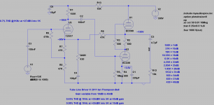
To do this you need to add another stage of gain because the SRPP on its own does not have enough gain to use NFB AND achieve 25 to 30dB. Here is the circuit of a design of mine that uses an ECC88 (6922) as an SRPP output stage with half of an ECC83 (12AX7) for the extra gain. You can set the gain to any value between 6 and 40dB by altering the GAIN resistor.
Cheers
Ian
Attachments
Wow Ian, possible is just but I looking for an adaptative gain in a preamp. Do you know the input/output impedance & how much V RMS swing when used with a gain of 25-31?
Last edited:
There is very little point adding a cathode follower to an SRPP.
Adding a CF after an SRPP effectively negates the push/pull aspect of the SRPP and basically leaves you with a half-mu amp; in other words, an Aikido-esque topology. Quite a nice topology really!
Wow Ian, possible is just but I looking for an adaptative gain in a preamp. Do you know the input/output impedance & how much V RMS swing when used with a gain of 25-31?
The input impedance is in excess of 470K. The output impedance is in the region of 150 ohms.
Cheers
Ian
Adding a CF after an SRPP effectively negates the push/pull aspect of the SRPP and basically leaves you with a half-mu amp; in other words, an Aikido-esque topology. Quite a nice topology really!
I thought the point of Aikido was its PSRR?
Cheers
Ian
- Status
- Not open for further replies.
- Home
- Amplifiers
- Tubes / Valves
- 6DJ8/ECC88-SRPP Tube Preamplifier