stephe,
I am glad you are back.
Good job on an amplifier.
Not your first, but a good low cost one.
But 'sounding good' counts for a lot.
I am glad you are back.
Good job on an amplifier.
Not your first, but a good low cost one.
But 'sounding good' counts for a lot.
Last edited:
HeyBill,
The two 100 Ohm resistors are a good thing to do (and very often commonly used):
1. It creates a virtual center tap to ground.
2. It makes the filament ends be 3.15V from ground (better than 6.3 to ground coupling to the grids via capacitance, and picking up high frequency noise).
High frequency noise generaly does not come from the primary to the secondaries, but high frequency noise can come from the B+ secondary, which has solid state rectifiers and a cap input filter, and therefore has sharp transients with lots of high frequency spectra. That can couple from secondary to secondary.
3. It keeps the filaments from floating to some unknown voltage.
And, high frequency noise on a floating filament winding can couple high frequencies from the filament to the input tube cathode (n this case that can be a problem, especially since the cathode has no bypass capacitor to ground.
Nuf said?
Last edited:
Are the resisters to ground in the heater for balance?
Merlin Blencowe has a good article on heater wiring on his Valve Wizard website:
The Valve Wizard
As 6A3sUMMER said, using resistors to create a virtual center tap on the transformer secondary is a fairly common practice.
Last edited:
I've got this amp running and it sounds good.
For safety, the bleeder resistor should be about ten times smaller in value, roughly 50k.
Then the HV will decay in around 30 seconds even unloaded. It should be rated for 2W or more.
Last edited:
Steph,
Nice work and keep posting!
I just build a 6BM8 for a buddy and built a 6GW8 (ECL86) for myself. I used a very small amount of plate to plate FB (sacrilege to many here) in both projects. They both sound awesome.

Nice work and keep posting!
I just build a 6BM8 for a buddy and built a 6GW8 (ECL86) for myself. I used a very small amount of plate to plate FB (sacrilege to many here) in both projects. They both sound awesome.
stephe, glad you got er done. Are the resisters to ground in the heater for balance?
It's something I picked up as a way to reduce hum when the transformer heater winding has no center tap, as a way of referencing them to ground instead of the A/C just floating.
Steph,
I used a very small amount of plate to plate FB (sacrilege to many here) in both projects.
Do you remember what size resistor you used? I've learned to play around with this, as it does affect the tone. I've used anywhere from 180k to 510K and found the lower the value, the more it tames any brightness. Too low and it starts sounding muddy.
For safety, the bleeder resistor should be about ten times smaller in value, roughly 50k.
Then the HV will decay in around 30 seconds even unloaded. It should be rated for 2W or more.
I considered this but I don't have the ma to spare. The transformer is rated at 71ma, the two pentodes use 62-64 even biased cool, the two triodes are pulling 2.6, that's 65ish. Another 4.5ma puts me right at the limit of the transformer rating, which IMHO isn't a good idea to leave no cushion. I get it will take several minutes to bleed down unloaded, but sometimes we have to make sacrifices when using off the shelf parts. If the transformer was rated at 100ma, I agree a smaller resistor would be better.
Steph,
I use something around 200k on dissimilar triode / pentode builds.
I have taken all of my schematics off the internet then adjusted them for what I think is optimal. I recently have build three different flea amps: 6CY7, 6BM8, and 6GW8. They last amp is by far my favorite. I have very good SET amps as reference to compare it with. Having said that, I think it sounds very good, but not until I added a bit of local, negative FB. My SET amps have no FB.
Keep up the good work and continue to encourage others.
Cheers,
Greg
Do you remember what size resistor you used? I've learned to play around with this, as it does affect the tone. I've used anywhere from 180k to 510K and found the lower the value, the more it tames any brightness. Too low and it starts sounding muddy.
I built an amp very similar to yours with 6BM8, albeit at a much higher B+ voltage (I didn't know better at the time). I used 330k, 2W for the plate-to-plate resistor. From then on I always use plate-to-plate FB on my amps. Wish I still had it.
Backtracking to the output impedance comments earlier in this thread...if I remember correctly, seeing SmokingAmps trace plots, plate-to-plate feedback will turn the pentode curves into something more akin to triode curves for the output circuit. As others have stated in this thread, triodes are not as sensitive to load impedance, so it stands to reason plate-to-plate FB would settle the output load issue.
OP, thank you for posting. I plan on watching you videos in the near future.
It's something I picked up as a way to reduce hum when the transformer heater winding has no center tap, as a way of referencing them to ground instead of the A/C just floating.
Steph,
If you have a center trap trafo, lifting the heaters with the cathode of the Pentode in these twin tubes can work wonders.
Cheers,
Greg
I built an amp very similar to yours with 6BM8, albeit at a much higher B+ voltage (I didn't know better at the time). I used 330k, 2W for the plate-to-plate resistor. From then on I always use plate-to-plate FB on my amps. Wish I still had it.
Backtracking to the output impedance comments earlier in this thread...if I remember correctly, seeing SmokingAmps trace plots, plate-to-plate feedback will turn the pentode curves into something more akin to triode curves for the output circuit. As others have stated in this thread, triodes are not as sensitive to load impedance, so it stands to reason plate-to-plate FB would settle the output load issue.
OP, thank you for posting. I plan on watching you videos in the near future.
Actual listening tells me that there is validity to this notion, they really can sound like a SET. Not quite as good, but close. For me it’s close enough that it is one of my summertime amps, and after a short listening session, I don’t miss my good SET amps.
Steph,
If you have a center trap trafo, lifting the heaters with the cathode of the Pentode in these twin tubes can work wonders.
Cheers,
Greg
Interesting. I would have to redo some wiring but I could use this virtual center tap to lift them. What "wonders" will I hear?
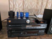
Finished the amp & videos
Well I got this project finished and have spent several hours listening to it.
It sounds fantastic! No hum whatsoever, and is a very musical amp. I still have a few mods I want to experiment with, especially on the input section cathode bias scheme, but I am super pleased how it sounds as built in that last posted schematic. For a super simple design, it turned out great but I would suggest if this is someone's first build, pick a chassis a little bigger than the one I used, it was a tight fit.
Uploaded the last two videos, one has the final wiring and voltage testing. The last is a basic scope test and discussing some future minor mods I want to try.
6BM8 DIY Stereo Tube Amplifier Series - YouTube
https://www.diyaudio.com/forums/attachment.php?attachmentid=957935&stc=1&d=1623031283
Attachments

Looking good. Yeah, there is no such critter as a large enough chassis. It's an oxymoron.
One simple thing you might want to try is to add an output Zobel. Mostly you don't notice it, but in a bad circumstance, like a speaker wire coming loose, or a bad RFI situation, it gives a layer of security. Good values for your design would be 10R/2W in series with 0u1F/63V across the 8 Ohm taps.
All good fortune,
Chris
I've enjoyed following this thread so I thought it might be interesting to model the amplifier in LTspice. The .asc simulation file is attached; this circuit includes the 300k plate-to-plate feedback resistor.
When fed a 1KHz square wave I got the same slight overshoot and ringing that Stephe saw on her scope (in video #16, I believe). See the plot attached. This is a good indication that the simulation results are pretty close to the real thing.
I also ran a simulation adding a 22 pF lead compensation capacitor across the 300k feedback resistor, and this tamed the overshoot and ringing. That simulation plot is also attached. In simulation, 10 pF looked like it was enough so you might want to experiment to see what actual minimum capacitance is needed to eliminate the ringing.
Great project!
Attachments


So you think that's a better approach that trying other values for the feedback resistor? I've never tried adding capacitance to a Schade feedback circuit but am happy to try and see what it sounds like.
- Home
- Amplifiers
- Tubes / Valves
- 6BM8 "tiny tube amp" build + Video Series